http://www.lcdwiki.com/Main_Page
https://www-elektroda-pl.translate.goog/rtvforum/topic1099191.html?_x_tr_sl=auto&_x_tr_tl=en&_x_tr_hl=en
https://kbiva.wordpress.com/2012/12/30/hp-laserjet-4500-front-panel/
https://kbiva.wordpress.com/2012/12/30/hp-laserjet-4500-front-panel/
https://playground.arduino.cc/Code/HpLaserJetLcd/
https://learn.sparkfun.com/tutorials/retired---using-the-logic-level-converter
https://forums.adafruit.com/viewtopic.php?t=22226
After making many microcontroller projects with character lcd’s(16×1,16×2) and interfacing them with variety of microcontrollers (arduino, microchip pin microcontroller,8051 series,stm32 etc). I still get emails from students about what is the difference between character lcd interfacing in 4-bit and 8-bit mode. So i decided why not to write a post on difference between lcd 4-bit and 8-bit mode interfacing.
In this short tutorial i will try to explain the basic difference between the two modes and the advantages/disadvantages in using the either of the two. This post will help the newbies putting their step in embedded field to easily understand the two modes. Character lcd’s come in many sizes 8×1 , 8×2 , 10×2 , 16×1 , 16×2 , 16×4 , 20×2 , 20×4 ,24×2 , 30×2 , 32×2 , 40×2 etc. Each character lcd has 8-bit data port to connect with external controllers. All the character lcds can be used in 8-bit as well as 4-bit mode.
I assume that you have an introduction to character lcds and know about their internal structure, pin out, registers, commands etc. If you don’t I recommend to first take the introduction tutorial and then resume with this post.
Since character lcd’s has 8 data pins so they accept only 8-bit data. Character datatype is 8-bit wide. So character values can easily be send to lcd. This mode is know as 8-bit mode in which we send an 8-bit value such as character or ASCII value to lcd.
In 4 bit mode only four data pins are used. Character 8-bit ASCII value is divided in to two 4-bit nibbles. High nibble is sent first following by the lower nibble. So in theory two strokes are needed to send a character(8-bit) to lcd when we are using lcd in 4-bit mode.
In contrast in 8-bit communication mode, 8-bit ASCII value of character is send in a single stroke to lcd.
Thus the 4-bit mode generates latency. Although 4-bit mode generates latency it on the other hand saves 4 gpio(general purpose input out pins) of the external controller sending data to lcd. Which can be utilized else where.
The gif animation below explains the difference between 4-bit and 8-bit mode very beautifully.

Lcd in 4-bit modeCommands used to initialize the 4-bit lcd mode
Some Projects made using character lcd in 4-bit mode. |
Lcd in 8-bit modeCommands used to initialize the 8-bit lcd mode are
Some Projects made using character lcd in 8-bit mode. |
https://www.engineersgarage.com/lcd-in-4-bit-mode-and-8-bit-mode/
Lcd sizesCharacter lcd’s come in many sizes 8×1, 8×2, 10×2, 16×1, 16×2, 16×4, 20×2, 20×4, 24×2, 30×2, 32×2, 40×2 etc . Many
multinational companies like Philips, Hitachi, Panasonic make their own
custom type of character lcd’s to be used in their products. All
character lcd’s performs the same functions(display characters numbers
special characters, ascii characters etc).Their programming is also same
and they all have same 14 pins (0-13) or 16 pins (0 to 15).
|


8×1 Character Lcd Rows and Columns

8×2 Character Lcd Rows and Columns
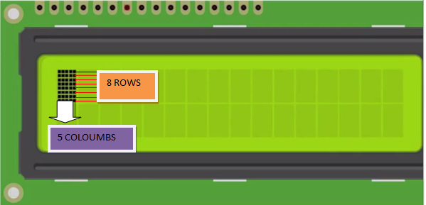
All character lcd’s have
16×2 lcd pin out diagrammatically is shown below.

Register select selects the HD44780 controller registers. It switches between Command and data register.
Lcd RW(Read/Write) Pin

nxn lcd initialization commands
NOTE: You can send commands in hexadecimal or decimal form which one do you like the result is same because the microcontroller translate the command in 8-bit binary value and sends it to the lcd.
Character Lcd’s can be used in 4-bit and 8-bit mode. Before
you send commands and data to your lcd. Lcd must first be initialized.
This initialization is very important for lcd that are made by Hitachi because
they use HD44780 driver chip sets. Hd44780 Chip set first has to be
initialized before using it. If you don’t initialize it properly you
will see nothing on your lcd.
For 8-bit mode, this is done as follows:
1. Wait more than 15 mill secs after power is applied.
2. Write command 0x30 to LCD and wait 5 milli seconds for the instruction to complete.
3. Write command 0x30 to LCD and wait 160 micro seconds for instruction to complete.
4. Write command 0x30 AGAIN to LCD and wait 160 micro seconds or Poll the Busy Flag.
In 4-bit mode the high nibble is sent first before the low nibble and the En pin is toggled each time four bits is sent to the LCD. To initialize in 4-bit mode:
1. Wait more than 15 mill secs after power is applied.
2. Write command 0x03 to LCD and wait 5 msecs for the instruction to complete.
3. Write command 0x03 to LCD and wait 160 usecs for instruction to complete.
4. Write command 0x03 AGAIN to LCD and wait 160 usecs (or poll the Busy Flag).
Write 0x02 to the LCD to Enable 4-Bit Mode
To learn more about the difference between 4-bit and 8-bit character lcd mode and operation with demo example visit the tutorial link given below. Demo examples are very easy to understand and one can make changes easily in the code. Please also give us your feed back on the post.
Custom
characters are self made characters which we design by our self. We
have full control on designing them with some constraints which i will
discuss later. Like if we want to display a smiley  on 16×2 lcd. We don’t have an ASCII character for smiley to display it on 16×2 lcd. Example of custom characters is below

Example of custom characters displayed on 16×2 lcd
16×2 lcd has an internal CG-RAM(character generated ram) in which we can generate or place our custom character. CG-RAM size is 64 bytes. We can generate/place 8 characters of size 5×8 at a time in CG-RAM. We can also place 5×10 size characters in CG-RAM but only 4.
5×8 represents the dimension of the matrix in which a
particular character can be displayed. 5 represents the number of
coulombs and 8 represents the number of rows. 5×8 combined is a matrix
size. Matrix is composed of pixels which we turn on and off to represent
or make a character. For example to display a smiley in 5×8 dimension individual pixels on and off will be same like below.

5×8 pixel dimension of custom character display
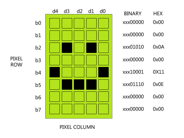
16×2 custom character smiley binary bits
The above binary or hex values are then arranged in a byte array. Byte array is then placed in to CG-RAM of 16×2 lcd. Now when we want to display this smiley character on lcd screen we just call its address in CG-RAM and finally the character will appear on 16×2 lcd screen.
I almost explained every thing above, about generating custom characters in 16×2 lcd CG-RAM and displaying them on lcd screen. But still their are few things which are not part of this tutorial. Like custom character address in CG-RAM. Its because the arduino ide has pre-defined library which places the custom characters in CG-RAM and call it when needed for display. If you want to know about whats happening behind the library then i recommend you to please learn about the custom character generation in internal hardware level first before proceeding.
In this project i am using 16×2 lcd in 4-bit mode so you have to make pin connections according to the 4-bit mode. Its not very hard just connect in the order given below.

The createChar() command in ardunio ide is very important. It creates/puts the character matrix/array against an addres in CG-RAM of 16×2 lcd. In other microcontrollers we have to write the memory address where we want to place our newly created custom character but in ardunio the createChar() command creates the required character automatically and place it against an address in CG-RAM. createChar() function is part of LiquidCrystal library. If we open the library and see the function statements they are communicating with the HD44780 lcd controller and CG-RAM address are defined in the function.
| #include<LiquidCrystal.h> | |||||||
| //Custom characters byte arrays |
| byte customchar[8]={B00000,B01010,B00000,B00000,B00000,B00000,B11111,}; |
| byte a[8]={B00000,B01010,B00100,B00100,B00000,B01110,B10001,}; |
| byte s[8]={B00100,B01010,B10001,B10001,B01010,B00100,}; |
| byte s1[8]={B01110,B01010,B11111,B11011,B11111,B01010,B01110,}; |
| byte s2[8]={B01010,B00100,B00100,B01010,B10001,B00100,B10001,}; |
| byte s3[8]={B00100,B01010,B11111,B01010,B10101,B11011,B10001,}; |
| byte s4[8]={0x1F,0x11,0x11,0x11,0x11,0x11,0x1F,}; |
| byte s5[8]={B11111,B11101,B11011,B11101,B11111,B10000,B10000,B10000,}; |
| //Custom characters byte arrays |
|
|
| void setup() |
| { |
| lcd.begin(16 ,2); //Initialize 16x2 lcd |
| lcd.clear(); //Clear lcd display screen |
|
|
| lcd.createChar(1 , customchar); //Creating custom characters in CG-RAM |
| lcd.createChar(2 , a); |
| lcd.createChar(3 , s); |
| lcd.createChar(4 , s1); |
| lcd.createChar(5 , s2); |
| lcd.createChar(6 , s3); |
| lcd.createChar(7 , s4); |
| lcd.createChar(8 , s5); //Creating custom characters in CG-RAM |
| } |
| void loop() |
| { |
| int rand,i; |
| lcd.setCursor(0 ,0); //Place lcd cursor on first row and first coulomb of 16x2 lcd |
| lcd.print("Cust Character!!"); //Display this test on first row on 16x2 lcd |
| lcd.setCursor(0 ,1); //Place lcd cursor on second row of 16x2 lcd first coulomb |
|
|
| for(rand=0;rand<10;rand++){ //For loop will display custom characters one by one |
| i=random(10); |
| lcd.setCursor(i ,1); |
| lcd.write(i); //-->>>PRINTING/DISPLAYING CUSTOM CHARACTERS |
| delay(500); |
| } |
| lcd.clear(); //Clear lcd and start again |
Numerous custom character generators are available online i usually use maxpromer its easy to use and biggest advantage of it is. It can generate whole arduino code in just seconds. Just give it a try i bet you gone love it.

More projects regarding custom characters, arduino and other microcontroller. All the projects are open source. Each and every statement with circuit diagram of the projects are well explained in the tutorials.
Part 2: https://www.engineersgarage.com/making-custom-characters-on-lcd-using-arduino/
This tutorial is about making/building your own characters/special images and then displaying them on character 16×2 lcd. Generating custom characters or special character images and displaying on lcds of any sizes (16×1,16×2,8×1,8×2,20×1,20×2,40×1,40×2 etc) is not a very hard task. One must go through the internal structure of lcd control set in order to know how the character lcd works? Once you know how the lcd works and what features it offers. Then you can easily build and display characters of your desire on lcd screen in a defined matrix.
It requires only knowledge of CG-RAM(character generated ram) of character lcd and the lcd chip set controller to build and display self made characters on 16×2 lcd display. Most of the lcds contains HD4478 controller in them. HD4478 controller is build by Hitachi and its the most popular controller used in the character lcd’s. Almost all of the character lcd’s resides one, but new competitors are also present in market.
By custom characters i mean characters that are not present in the
ASCII character set of lcd controller. Like heart symbol, smiley 

 etc. We have to declare these custom characters in CG-RAM of lcd by our
own. This tutorial will teach you how to declare custom characters in
CG-RAM and then call display them one by one to display on 16×2 lcd
screen.
etc. We have to declare these custom characters in CG-RAM of lcd by our
own. This tutorial will teach you how to declare custom characters in
CG-RAM and then call display them one by one to display on 16×2 lcd
screen.
CG-RAM is the main component in making custom characters. CG stands for custom generated and RAM you all know random access memory. This CG-RAM stores our custom characters once we declare them in our code. I will come on it later. As you know once we write any type of code we need a memory to store it and a controller to run it. In the 16×2 lcd custom character case its same. We write code(arrays) of character’s which we want to display on lcd. Then we store them in a memory on lcd. In our case this memory is named as CG-RAM(Character generated RAM).
CG-RAM size is 64 Bytes. You can create 8 characters at a time and load them in cg-ram. Each character occupies 8-bytes. Eight characters each of eight byte (8-characters * 8-Bytes) is equal to 8×8=64 Bytes. CG-RAM address in lcd memory starts from 0x40(Hexadecimal) or 64 in decimal.
You can place your first character in address ranging from 0x40 to 0x47. The address moves on by 8 bytes for each character for 2nd character address starts from 0x48 and goes to 0x4F. Last eight’t character address starts from 0x78 and goes to 0x7F.
CG-RAM character addresses and commands

Here is a simple example on how to generate pixels array for letter ‘b‘ and then place it in CG-RAM of character 16×2 lcd display.
The Array for generating letter ‘b‘ is
char b[7]={0x10,0x10,0x16,0x19,0x11,0x11,0x1E};
We now have some online websites through which you can get array of your
desired image in 5×7 or 5×8 format. One of the most popular is maxpromer.
You can graphically input your desired image on a matrix in maxpromer
and then with a single button press you get the array of the image. The
array can further be used in your code.

In the above picture you can see the interface of maxpromer. Pretty simple and easy to use. In just seconds you can generate the matrix array for your input character. Array can be generated in binary as well as hexadecimal format.
What individual bits represent in array really needs to be understood. ‘0‘ represents pixel is off and ‘1‘ represent pixel is on. Like for the letter ‘b‘ whose array was highlighted above. Its representation is given below. For each row we have a binary or hexadecimal representation. In binary representation we ignore the 3 MSB or most significant bits, because the coulombs of the matrix are 5. So 5 LSB least significant bits are considered. Also in hexadecimal representation the 3 MSB don’t matter. In the below picture the array of letter ‘b‘ is placed against address ranging from 0x40 to 0x47. Row-1 is placed at address 0x40, row-2 is placed at 0x41, then row-3 is placed at 0x42 and so on until row-7 against address 0x47.

|
|
| lcdcommand(0x40); //Notifying CG-RAM for incoming custom character and its address |
|
|
| while(i!=7) //Placing 'b' By sending 'b' pattern to cg-ram |
| { |
| lcddata(b[i]); |
| i++; |
| } |
|
|
| char b[7]={0x10,0x10,0x16,0x19,0x11,0x11,0x1E}; //'b' character pattern placed in code |
Important: Just to let you know that commands(like 0x40 address of cg-ram) are send to command register of lcd and data like ‘b‘ pattern is send to data register of lcd.
The above code can be divide in to steps
Part 1: https://www.engineersgarage.com/making-custom-characters-on-16x2-lcd/
 |
Arduino Uno or equivalent. This chapter accepts any other Arduino board. |
 |
A solderless Breadboard. |
 |
Some jumper wires. |
 |
A Potentiometer. |
 |
A 16×2 or 16×4 LCD display. |
The 7-segment LED displays, we saw in the previous chapter, are fine, they are cheap and practical, but have the disadvantage that they can not display text messages, only numbers.
But we can miss some system to display simple text messages, and so the LCD displays were built. They are easy to find in different formats: 16 × 2 (16 columns x 2 rows) or 16 × 4 (16 columns x4 rows).
Basically because:
In this chapter we will see how to connect them to your Duinos and how to use them to send messages to the outside world.
Although, lately, these displays are usually sold with the pin strip
welded, there are still many places that sell them as a kit, with the
pin strip unwelded.

The first thing you have to know is that you do have to weld them, you can not just stick them together more or less wildly. You do have to weld them. Get used to it. Any other solution would end up malfunctioning or directly burning out the display.
When you have it ready, stick the display on the breadboard, leaving
room for other components and wires. Remember that there will be many of
them, so be generous with the room you leave.
Here you have the circuit wiring diagram:

And this is the wiring diagram for the solderless breadboard:

The connection is not complicated, but you have to be careful. So let’s go step by step connecting the different cables. Start connecting Vcc and GND to the breadboard.

Let’s now power up the LCD panel. Connect the pin16 of the LCD to Ground and the pin 15 to 5V

If you connect now the USB cable to your Duino, the LCD should light, if not, check your wires before proceeding.
Let’s connect now the adjustment potentiometer. Connect one end of the pot to GND, the other end to 5V and the center pin to the pin 3 of the LCD.
We will also take advantage to turn on the LCD panel, so connect the pin 1 to GND and the Vcc to pin 2:

If all went well, we can turn the display and test it. Connect the USB to your Arduino and let’s see. If you’re turning the potentiometer, at some point you have to see some squares on the screen, otherwise check the connections. Do not go ahead if you do not see it.

If you see the arrays of dots on the screen, we can continue.
We will now connect the data and control pins. Without going into many details, we will not use all available pins because we do not need them. We will only use two control pins, RS (Register Select) and EN (Enable), and the 4 data pins D7, D6, D5 and D4. We do not need more for now.
Let’s keep on with the control connections:
RW, LCD pin 5             GND
RS, LCD pin 4             Arduino pin 7
EN, LCD pin 6             Arduino pin 8
And now the data wires.
DB7, LCD pin 14          Arduino pin 12
DB6, LCD pin 13          Arduino pin 11
DB5, LCD pin 12          Arduino pin 10
DB4, LCD pin 11          Arduino pin  9

Let’s use a library to control the LCD display, which is included in our Arduino. Go to:
\\Sketch\Add library...\LiquidCrystal
And now we can import one of the examples or write our own sketch, commenting the code. when we import the library we will see the following line:
#include <LiquidCrystal.h>
Then, you must initialize the library. To do it we create an LiquidCrystal object instance, called LCD, and pass it as parameters the pins that have defined:
LiquidCrystal lcd(7, 8, 9, 10, 11, 12); // ( RS, EN, d4, d5, d6, d7)
The rest is easy.
void setup()
   {
       lcd.begin(16, 2);            // Set the number of rows and columns
       lcd.print("Prometec.org");   // Send the message
   }

void loop()
   {
       lcd.setCursor(0, 8);         // Set the cursor to column 0, line 1
       lcd.print(millis() / 1000);  // Print the number of seconds since reset:
   }
These display are hard to wire, but very simple to use.
Let’s try to make a clock (very simple so far). If you remember the functions we have used in recent chapters, we can recover some of them to show the value of the millis() function as if it were a clock.
Sketch 41.1#include <LiquidCrystal.h>
LiquidCrystal lcd(7, 8, 9, 10, 11, 12);
void setup()
{
lcd.begin(16, 2); // Set the number of rows and columns
lcd.print("Prometec.org"); // Send the message
}
void loop()
{
lcd.setCursor(6, 1); // Locate the position in the row 1, column 6
String s = clock();
lcd.print(s) ;
}
String reloj()
{
int n = millis() / 1000 ; // We convert it to seconds
int seconds = n % 60 ;
int minutes = n / 60 ;
String S = String(minutes) + ":" + String(seconds);
return (S);
}
It is worth commenting some things in this code. First, in the clock function we have calculated the minutes and seconds from the Arduino internal clock in milliseconds, there is nothing new here. But look, we have defined clock as a String variable:
String clock()
That means that we will return a String type parameter. At some point the function will have to use a return (String) statement.
Notice that we have defined a string called s within the function:
String S = String(minutes) + ":" + String(seconds);
In this line you should not confuse (though they are written exactly the same), the String type used to define the string variable S on the left, with the String(n) function, that converts a number n in a text string, so we can concatenate the number of minutes and seconds into a text string using a semicolon character.
At the end we add a couple of blank spaces, to avoid dragging ghosts on the screen
Inside the loop() function, we have used the following statement to show the text string:
lcd.print(s) ;
Everything that you already know of the Serial.print() function is equally valid for this instruction. And finally, we have the following line:
lcd.setCursor(6, 1); // Ponte en la line 1, posicion 6
What it does is to position the cursor on the display, in the column 6
of the second line to write the time centered. Here you have a mini
video with the result.
The LCD library includes several interesting examples that you should try. Remember, you have simply to change the definitions of the pins in order to work properly..
A particularly interesting example is CustomCharacter, which defines a set of special characters and moves them around the screen, depending on the values read from a potentiometer.
Without going into too much sophistication, it is very interesting to
see how to define some special characters, because in the character’s
table of the LCD are not included symbols as ñ, accents, degrees or even
€. So, just in case, it could be interesting to know how to define your
own symbols.
Let’s define our own character, the degree symbol, for example.
The first thing you have to know is that the characters are defined as an 8 × 8 array (yes, again), as if you draw it in a grid of that size, filling the full little square.
For example, in order to draw the degree symbol we will define it this way:

byte degree[8] =
 {
    0b00001100,     // We define them as binary numbers 0bxxxxxxx
    0b00010010,
    0b00010010,
    0b00001100,
    0b00000000,
    0b00000000,
    0b00000000,
    0b00000000
 };
To load the character in the character’s table of the LCD we will use the following statement:
lcd.createChar(0, euro);
lcd.createChar(1, degree);
And now it is already available. Please note that we can only define eight special characters in a given time (although we can define 30 arrays of characters, create them and destruct them on the fly).
Here is an example of the sketch:
#include <LiquidCrystal.h>
LiquidCrystal lcd(7, 8, 9, 10, 11, 12);

byte degree[8] =
 {
     0b00001100,
     0b00010010,
     0b00010010,
     0b00001100,
     0b00000000,
     0b00000000,
     0b00000000,
     0b00000000
 };

void setup()
  {
      lcd.begin(16, 2); // We initialize the LCD
      lcd.createChar(1, degree);
      lcd.setCursor(0, 0);
      lcd.print("Temperature 25");
      lcd.write(1);
      lcd.print("C");
}

void loop() { }
And here you have a photograph showing the result:
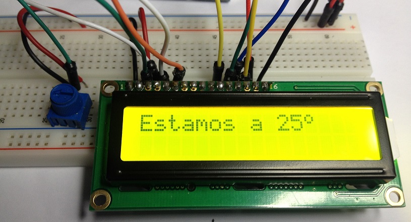
Finally, and to close the chapter (everything comes in life), I have to tell you again that we have assembled this display in the hard way, connecting a lot of wires.
All this work can only be justified because one day I swallowed the bait and bought a one of these displays (actually two. I have also a 16 × 4 display), but if you are going to buy an LCD display, for God’s sake, buy one I2C display or something like that, your mental health will improve a lot and you will only have to use 4 wires.
In the next chapter we will assemble one of them for you to see the difference.
Sources: http://prometec.org/displays/lcd-displays/
