Objectives
- We are going to connect a 16×2 LCD display to our Arduino.
- We will see how to show information on the display
- We will see how to define some special characters.
Bill of materials
 |
Arduino Uno or equivalent. This chapter accepts any other Arduino board. |
 |
A solderless Breadboard. |
 |
Some jumper wires. |
 |
A Potentiometer. |
 |
A 16×2 or 16×4 LCD display. |
LCD displays
The 7-segment LED displays, we saw in the previous chapter, are fine, they are cheap and practical, but have the disadvantage that they can not display text messages, only numbers.
But we can miss some system to display simple text messages, and so the LCD displays were built. They are easy to find in different formats: 16 × 2 (16 columns x 2 rows) or 16 × 4 (16 columns x4 rows).
- LCD stands for Liquid Crystal Display.
Basically because:
- They are cheap.
- They are available in several sizes and configurations.
- They are low consumption devices.
- They are very practical, if you only have to show alphanumeric characters (and perhaps some special characters).
In this chapter we will see how to connect them to your Duinos and how to use them to send messages to the outside world.
BEFORE STARTING
Although, lately, these displays are usually sold with the pin strip
welded, there are still many places that sell them as a kit, with the
pin strip unwelded.
- At some point we will have to talk about how to weld components, but that day has not yet arrived..

The first thing you have to know is that you do have to weld them, you can not just stick them together more or less wildly. You do have to weld them. Get used to it. Any other solution would end up malfunctioning or directly burning out the display.
When you have it ready, stick the display on the breadboard, leaving
room for other components and wires. Remember that there will be many of
them, so be generous with the room you leave.
CIRCUIT WIRING DIAGRAM
Here you have the circuit wiring diagram:

And this is the wiring diagram for the solderless breadboard:

The connection is not complicated, but you have to be careful. So let’s go step by step connecting the different cables. Start connecting Vcc and GND to the breadboard.

Let’s now power up the LCD panel. Connect the pin16 of the LCD to Ground and the pin 15 to 5V

If you connect now the USB cable to your Duino, the LCD should light, if not, check your wires before proceeding.
Let’s connect now the adjustment potentiometer. Connect one end of the pot to GND, the other end to 5V and the center pin to the pin 3 of the LCD.
We will also take advantage to turn on the LCD panel, so connect the pin 1 to GND and the Vcc to pin 2:

If all went well, we can turn the display and test it. Connect the USB to your Arduino and let’s see. If you’re turning the potentiometer, at some point you have to see some squares on the screen, otherwise check the connections. Do not go ahead if you do not see it.

If you see the arrays of dots on the screen, we can continue.
We will now connect the data and control pins. Without going into many details, we will not use all available pins because we do not need them. We will only use two control pins, RS (Register Select) and EN (Enable), and the 4 data pins D7, D6, D5 and D4. We do not need more for now.
Let’s keep on with the control connections:
RW, LCD pin 5             GND
RS, LCD pin 4             Arduino pin 7
EN, LCD pin 6             Arduino pin 8
And now the data wires.
DB7, LCD pin 14          Arduino pin 12
DB6, LCD pin 13          Arduino pin 11
DB5, LCD pin 12          Arduino pin 10
DB4, LCD pin 11          Arduino pin  9

THE CONTROL PROGRAM
Let’s use a library to control the LCD display, which is included in our Arduino. Go to:
\\Sketch\Add library...\LiquidCrystal
And now we can import one of the examples or write our own sketch, commenting the code. when we import the library we will see the following line:
#include <LiquidCrystal.h>
Then, you must initialize the library. To do it we create an LiquidCrystal object instance, called LCD, and pass it as parameters the pins that have defined:
LiquidCrystal lcd(7, 8, 9, 10, 11, 12); // ( RS, EN, d4, d5, d6, d7)
- Be careful because the pins that have used do not correspond to
the pins used in the examples of the LiquidCrystal library. You can
change them, given the case, but ensure that you also change the pins in
the definition, or the sketch will not run..
The rest is easy.
void setup()
   {
       lcd.begin(16, 2);            // Set the number of rows and columns
       lcd.print("Prometec.org");   // Send the message
   }

void loop()
   {
       lcd.setCursor(0, 8);         // Set the cursor to column 0, line 1
       lcd.print(millis() / 1000);  // Print the number of seconds since reset:
   }
These display are hard to wire, but very simple to use.
Let’s try to make a clock (very simple so far). If you remember the functions we have used in recent chapters, we can recover some of them to show the value of the millis() function as if it were a clock.
Sketch 41.1#include <LiquidCrystal.h>
LiquidCrystal lcd(7, 8, 9, 10, 11, 12);
void setup()
{
lcd.begin(16, 2); // Set the number of rows and columns
lcd.print("Prometec.org"); // Send the message
}
void loop()
{
lcd.setCursor(6, 1); // Locate the position in the row 1, column 6
String s = clock();
lcd.print(s) ;
}
String reloj()
{
int n = millis() / 1000 ; // We convert it to seconds
int seconds = n % 60 ;
int minutes = n / 60 ;
String S = String(minutes) + ":" + String(seconds);
return (S);
}
It is worth commenting some things in this code. First, in the clock function we have calculated the minutes and seconds from the Arduino internal clock in milliseconds, there is nothing new here. But look, we have defined clock as a String variable:
String clock()
That means that we will return a String type parameter. At some point the function will have to use a return (String) statement.
Notice that we have defined a string called s within the function:
String S = String(minutes) + ":" + String(seconds);
In this line you should not confuse (though they are written exactly the same), the String type used to define the string variable S on the left, with the String(n) function, that converts a number n in a text string, so we can concatenate the number of minutes and seconds into a text string using a semicolon character.
At the end we add a couple of blank spaces, to avoid dragging ghosts on the screen
- Remove the blank spaces and look what happens when minutes
change. How would you solve it, without using the trick of putting those
blank spaces at the end? Think about it.
Inside the loop() function, we have used the following statement to show the text string:
lcd.print(s) ;
Everything that you already know of the Serial.print() function is equally valid for this instruction. And finally, we have the following line:
lcd.setCursor(6, 1); // Ponte en la line 1, posicion 6
What it does is to position the cursor on the display, in the column 6
of the second line to write the time centered. Here you have a mini
video with the result.
The LCD library includes several interesting examples that you should try. Remember, you have simply to change the definitions of the pins in order to work properly..
A particularly interesting example is CustomCharacter, which defines a set of special characters and moves them around the screen, depending on the values read from a potentiometer.
Without going into too much sophistication, it is very interesting to
see how to define some special characters, because in the character’s
table of the LCD are not included symbols as ñ, accents, degrees or even
€. So, just in case, it could be interesting to know how to define your
own symbols.
DEFINING OUR OWN CHARACTERS
Let’s define our own character, the degree symbol, for example.
The first thing you have to know is that the characters are defined as an 8 × 8 array (yes, again), as if you draw it in a grid of that size, filling the full little square.
For example, in order to draw the degree symbol we will define it this way:

byte degree[8] =
 {
    0b00001100,     // We define them as binary numbers 0bxxxxxxx
    0b00010010,
    0b00010010,
    0b00001100,
    0b00000000,
    0b00000000,
    0b00000000,
    0b00000000
 };
To load the character in the character’s table of the LCD we will use the following statement:
lcd.createChar(0, euro);
lcd.createChar(1, degree);
And now it is already available. Please note that we can only define eight special characters in a given time (although we can define 30 arrays of characters, create them and destruct them on the fly).
Here is an example of the sketch:
#include <LiquidCrystal.h>
LiquidCrystal lcd(7, 8, 9, 10, 11, 12);

byte degree[8] =
 {
     0b00001100,
     0b00010010,
     0b00010010,
     0b00001100,
     0b00000000,
     0b00000000,
     0b00000000,
     0b00000000
 };

void setup()
  {
      lcd.begin(16, 2); // We initialize the LCD
      lcd.createChar(1, degree);
      lcd.setCursor(0, 0);
      lcd.print("Temperature 25");
      lcd.write(1);
      lcd.print("C");
}

void loop() { }
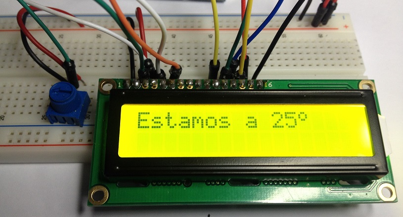
And here you have a photograph showing the result:
Finally, and to close the chapter (everything comes in life), I have to tell you again that we have assembled this display in the hard way, connecting a lot of wires.
All this work can only be justified because one day I swallowed the bait and bought a one of these displays (actually two. I have also a 16 × 4 display), but if you are going to buy an LCD display, for God’s sake, buy one I2C display or something like that, your mental health will improve a lot and you will only have to use 4 wires.
In the next chapter we will assemble one of them for you to see the difference.
SUMMARY
- We have seen the 16×2 LCD displays.
- It has been hard enough to understand that, as an exercise, it is fine, but we’ll see other less laborious ways to use these kind of displays.
- There exist also 16×4 displays (16 columns and 4 lines), just in case you need more room in the display.
- They are very comfortable to use because we can print alphanumeric texts directly, like a serial port.
- We can (and we will have to do it, surely) also define characters and symbols not included in the display.
Sources: http://prometec.org/displays/lcd-displays/
Không có nhận xét nào:
Đăng nhận xét