In this tutorial, we will see how to interface DS1307(RTC) with 8051.
First, we will see the internals of DS1307 and later how to read and write the date and time.
DS1307 Basics
The Real-time clock DS1307 IC basically is stand-alone time clock with following features.
- Real-time clock (RTC) counts seconds, minutes, hours, date of the
month, month, the day of the week, and year with leap-year compensation
valid up to 2100.
- The clock operates in either the 24-hour or 12-hour format with AM/PM indicator.
- 56-byte, battery-backed, non-volatile (NV) RAM for data storage
- Two-wire(I2C) serial interface
- Programmable squarewave output signal
- Automatic power-fail detect and switch circuitry
- Consumes less than 500nA in battery backup mode with oscillator running
- Optional industrial temperature range: -40°C to +85°C
DS1307 Pins
Below image shows the pin diagram and the recommended connections for DS1307.
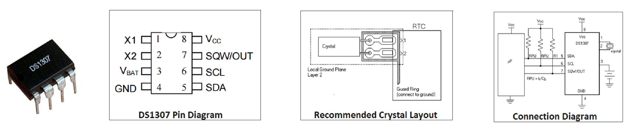 VCC, GND: These pins are used to provide the power to the chip.
When 5V is applied within normal limits, the device is fully accessible
and data can be written and read. When a 3V battery is connected to the
device and VCC is below 1.25 x VBAT, reads and writes are inhibited.
However, the timekeeping function continues unaffected by the lower
input voltage. As VCC falls below VBAT the RAM and timekeeper are
switched over to the external power supply (nominal 3.0V DC) at VBAT.
VCC, GND: These pins are used to provide the power to the chip.
When 5V is applied within normal limits, the device is fully accessible
and data can be written and read. When a 3V battery is connected to the
device and VCC is below 1.25 x VBAT, reads and writes are inhibited.
However, the timekeeping function continues unaffected by the lower
input voltage. As VCC falls below VBAT the RAM and timekeeper are
switched over to the external power supply (nominal 3.0V DC) at VBAT.
X1-X2:Pins to connect the external 32.768kHz oscillator that provides the clock source to the chip.
Vbat: A 3.3v Lithium battery can be connected to this pin
in order to provide the power source when the external supply voltage is
not available. Battery voltage must be held between 2.0V and 3.5V for
proper operation.
SCL: This pin must be connected to SCL pin of the I2C Bus/Master.
SDA: This pin must be connected to SDA pin of the I2C Bus/Master.
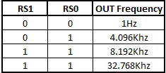
SQW/OUT: When enabled, the SQWE bit set to 1, the SQW/OUT pin
outputs one of four square wave frequencies (1Hz, 4kHz, 8kHz, 32kHz).
- Note: The SCL,SDA, and SQW are open drain and must be pulled up with appropriate pull-up resistors as shown in the image.
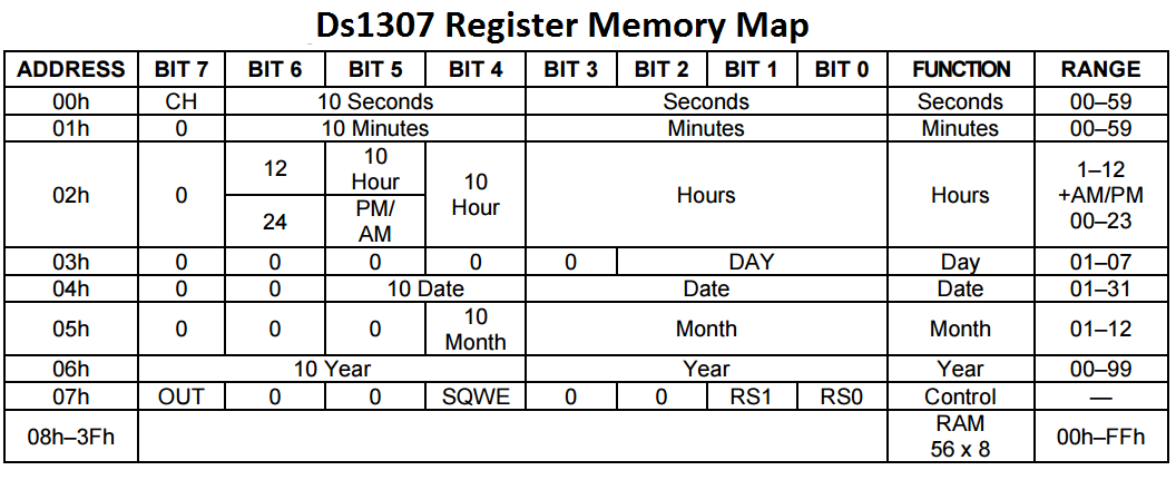
DS1307 Memory
The RTC keeps the date and time arranged in it's memory as shown below:
| Control Register
|
| 7 |
6 |
5 |
4 |
3 |
2 |
1 |
0
|
| OUT |
0 |
0 |
SQWE |
0 |
0 |
RS1 |
RS0
|
OUT: This bit controls the output level of the SQW/OUT pin
when the square-wave output is disabled. If SQWE = 0, the logic level on
the SQW/OUT pin is 1 if OUT = 1 and is 0 if OUT = 0. By default this
pin will be 0.
SQWE:This bit, when set to logic 1, enables the oscillator
output. The frequency of the square-wave output depends on the value of
the RS0 and RS1 bits.
RS1-RS0:These bits control the frequency of the square-wave output when the squarewave output has been enabled.
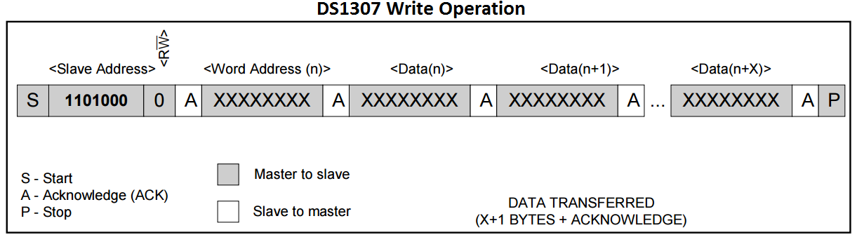
DS1307 ID
| Ds1307 ID
|
| 7 |
6 |
5 |
4 |
3 |
2 |
1 |
0
|
| 1 |
1 |
0 |
1 |
0 |
0 |
0 |
R/W
|
- R/W is 0 then data is Written to RTC
- R/W is 1 then data is Read from RTC
This is defined in the code as:
- #define C_Ds1307ReadMode_U8 0xD1u // DS1307 ID in read mode
- #define C_Ds1307WriteMode_U8 0xD0u // DS1307 ID in write mode
Steps to initialize DS1307
- Start the I2C communication.
- Send the DS1307 address and select write operation
- Send the Address of Control Register for sending the command.
- Send the Command to Disable the SQW Out.
- Stop the Communication.
- void RTC_Init(void)
- {
- I2C_Init(); // Initialize the I2c module.
- I2C_Start(); // Start I2C communication
-
- I2C_Write(C_Ds1307WriteMode_U8); // Connect to DS1307 by sending its ID on I2c Bus
- I2C_Write(C_Ds1307ControlRegAddress_U8);// Select the Ds1307 ControlRegister to configure Ds1307
-
- I2C_Write(0x00); // Write 0x00 to Control register to disable SQW-Out
-
- I2C_Stop(); // Stop I2C communication after initializing DS1307
- }
Steps to Write Date and Time
- Start the I2C communication.
- Send the DS1307 address and select write operation
- Send the Address of SECOND Register for writing the second value.
- Write the Sec,min,hour,weekDay,date,month,year one by one.
- Stop the Communication.
- void RTC_SetDateTime(rtc_t *rtc)
- {
- I2C_Start(); // Start I2C communication
-
- I2C_Write(C_Ds1307WriteMode_U8); // connect to DS1307 by sending its ID on I2c Bus
- I2C_Write(C_Ds1307SecondRegAddress_U8); // Request sec RAM address at 00H
-
- I2C_Write(rtc->sec); // Write sec from RAM address 00H
- I2C_Write(rtc->min); // Write min from RAM address 01H
- I2C_Write(rtc->hour); // Write hour from RAM address 02H
- I2C_Write(rtc->weekDay); // Write weekDay on RAM address 03H
- I2C_Write(rtc->date); // Write date on RAM address 04H
- I2C_Write(rtc->month); // Write month on RAM address 05H
- I2C_Write(rtc->year); // Write year on RAM address 06h
-
- I2C_Stop(); // Stop I2C communication after Setting the Date
- }
Steps to Read Date and Time
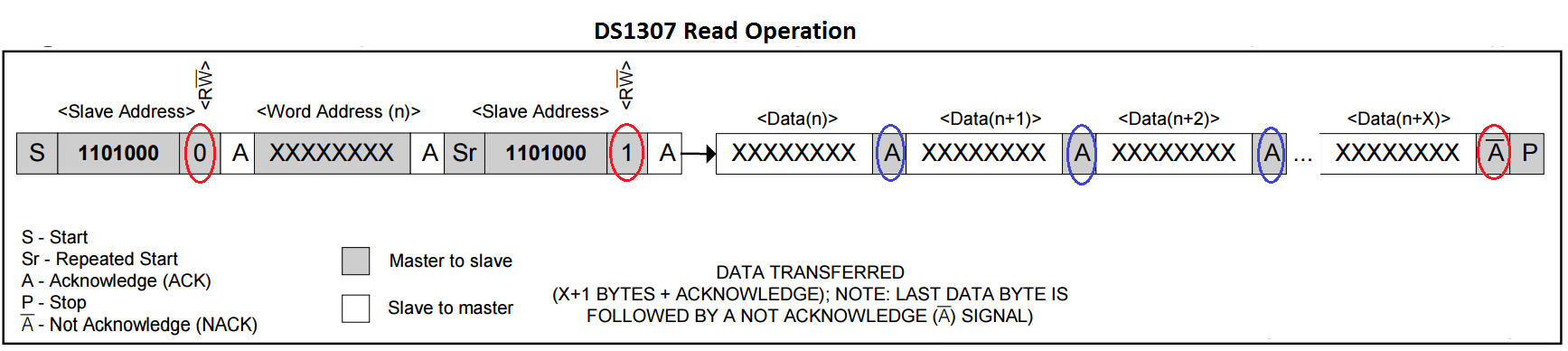
- Start the I2C communication.
- Send the DS1307 address and select write operation
- Send the Address of SECOND Register for reading the second value.
- Stop the Communication.
- Send the DS1307 address and select Read operation
- Read the Sec,min,hour,weekDay,date and month one by one and send positive acknowledgement.
- Read the Year and send the Neg/No Acknowledgement.
- Stop the Communication.
- void RTC_GetDateTime(rtc_t *rtc)
- {
- I2C_Start(); // Start I2C communication
-
- I2C_Write(C_Ds1307WriteMode_U8); // connect to DS1307 by sending its ID on I2c Bus
- I2C_Write(C_Ds1307SecondRegAddress_U8); // Request Sec RAM address at 00H
-
- I2C_Stop(); // Stop I2C communication after selecting Sec Register
-
- I2C_Start(); // Start I2C communication
- I2C_Write(C_Ds1307ReadMode_U8); // connect to DS1307(Read mode) by sending its ID
-
- rtc->sec = I2C_Read(1); // read second and return Positive ACK
- rtc->min = I2C_Read(1); // read minute and return Positive ACK
- rtc->hour= I2C_Read(1); // read hour and return Negative/No ACK
- rtc->weekDay = I2C_Read(1); // read weekDay and return Positive ACK
- rtc->date= I2C_Read(1); // read Date and return Positive ACK
- rtc->month=I2C_Read(1); // read Month and return Positive ACK
- rtc->year =I2C_Read(0); // read Year and return Negative/No ACK
-
- I2C_Stop(); // Stop I2C communication after reading the Date
- }
Both the above functions use a simple structure shown below for easy access
- typedef struct
- {
- uint8_t sec;
- uint8_t min;
- uint8_t hour;
- uint8_t weekDay;
- uint8_t date;
- uint8_t month;
- uint8_t year;
- }rtc_t;
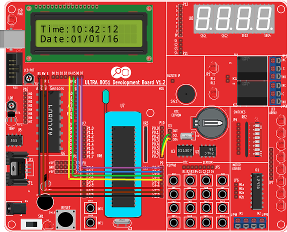
Hardware Connections
Code
Now, let's put together all that we have discussed in a simple example to read and show the time on character LCD.
Note: The date and time read from Ds1307 will be of BCD format, like:
- 0x12,0x39,0x26 for 12hr,39min and 26sec.
- 0x15,0x08,0x47 for 15th day,8th month and 47th year
 VCC, GND: These pins are used to provide the power to the chip.
When 5V is applied within normal limits, the device is fully accessible
and data can be written and read. When a 3V battery is connected to the
device and VCC is below 1.25 x VBAT, reads and writes are inhibited.
However, the timekeeping function continues unaffected by the lower
input voltage. As VCC falls below VBAT the RAM and timekeeper are
switched over to the external power supply (nominal 3.0V DC) at VBAT.
VCC, GND: These pins are used to provide the power to the chip.
When 5V is applied within normal limits, the device is fully accessible
and data can be written and read. When a 3V battery is connected to the
device and VCC is below 1.25 x VBAT, reads and writes are inhibited.
However, the timekeeping function continues unaffected by the lower
input voltage. As VCC falls below VBAT the RAM and timekeeper are
switched over to the external power supply (nominal 3.0V DC) at VBAT.


Không có nhận xét nào:
Đăng nhận xét