The name “potentiostat” describes its function. “Potentio” refers to
electrical potential, and “stat” stems from the Greek word “stato,”
which means standing or set.
As you can control the temperature of a room using a “thermostat,” a
potentiostat can control the potential of a single working electrode in a
3-electrode system, and is sometimes referred to as a “single-channel
potentiostat.” A potentiostat where the potential of 2 working
electrodes can be controlled independent of each other is referred to as
a “bipotentiostat.”
Potentiostats with more than two working electrode channels are
referred to as a “Multichannel Potentiostat.” A galvanostat refers to
an instrument that controls the current at an electrode rather than the
potential. Most modern potentiostats have galvanostat functionality
built in. The phrase "electrochemical workstation" also refers to a
potentiostat, and to our knowledge, the phrase is only used for
marketing purposes.
------------------
1What is a Potentiostat?
A potentiostat is an analytical
instrument designed to control the working electrode's potential in a
multiple electrode electrochemical cell. The potentiostat contains many
internal circuits that allow it to function in this capacity. The
circuits generate and measure potentials and currents. External wires
in a cell cable connect the potentiostat circuit to the electrodes in
the electrochemical cell. In a conventional three-electrode cell, the cell cable connects to the working, counter (auxiliary), and reference electrodes
on one end and the potentiostat cell cable connector on the other end.
The internal circuitry of the potentiostat controls the applied
signal. In the case of potential controlled methods, for example, the
working electrode's potential is held with respect to the reference
electrode. At the same time, current flows between working and counter
electrodes. The potentiostat circuit design prevents all but a tiny
current from flowing between the working and the high impedance
reference electrode. While modern potentiostats are more complicated
than can be explained in this article, a brief introduction to
potentiostat circuitry will be discussed to help you understand how a
potentiostat works.
It's not uncommon that
terminology gets confusing when discussing electrochemistry. Below is a
short note on potentiostat terminology. This can be useful if you are
purchasing a potentiostat and want to know all the equipment the
potentiostat comes with. If you are interested in purchasing a
potentiostat, you might want to check out our guide to purchasing a potentiostat article. Additionally we offer a variety of potentiostats for purchase.
The name “potentiostat” describes
its function. “Potentio” refers to electrical potential, and “stat”
stems from the Greek word “stato,” which means standing or set. As you
can control the temperature of a room using a “thermostat,” a
potentiostat can control the potential of a single working electrode in a
3-electrode system, and is sometimes referred to as a “single-channel
potentiostat.” A potentiostat where the potential of 2 working
electrodes can be controlled independent of each other is referred to as
a “bipotentiostat.”
Potentiostats with more than two working electrode channels are
referred to as a “Multichannel Potentiostat.” A galvanostat refers to
an instrument that controls the current at an electrode rather than the
potential. Most modern potentiostats have galvanostat functionality
built in. The phrase "electrochemical workstation" also refers to a
potentiostat, and to our knowledge, the phrase is only used for
marketing purposes.
The core electronic component of
a potentiostat is the operational amplifier, or op-amp for short. When
part of the op-amp output signal is fed into itself, it creates a
feedback mechanism. Feedback is the mechanism by which the potentiostat
can control the potential of the working electrode. Conceptually, one
can think about feedback like driving a car. While driving, you want to
maintain a constant distance between you and the car in front of you.
As the distance between you and the car changes, you adjust your speed
to maintain a safe distance. You are using the visual feedback from the
car to adjust your speed. In this analogy, the distance between you
and the car is the potential, and changing your car's speed (via slowing
down and accelerating) is the op-amp.
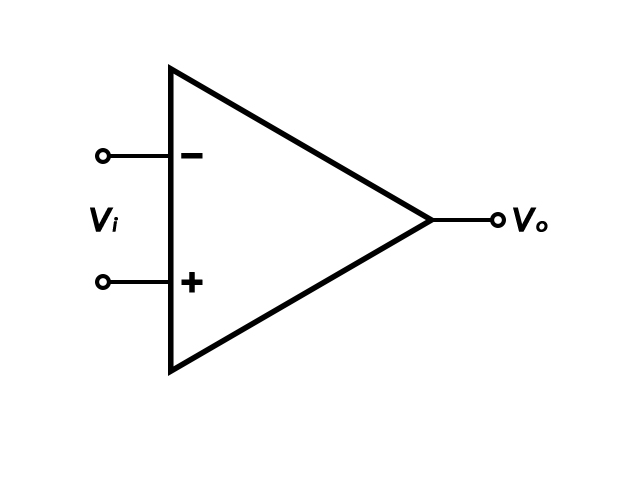
An operational amplifier, is
an electronic circuit component powered by a DC voltage capable of
amplifying an input voltage. Schematically, the op-amp symbol is a
sideways triangle with inputs along the vertical line and the output at
the point opposite the inputs (Figure 1). The voltage input to the
op-amp is a differential value between two potential inputs, ∈+ (non-inverting input) and ∈- (inverting
input), both of which are referenced to ground potential. The open
loop gain of the amplifier is a scalar factor (β), and common
amplifications are on the order of 105 - 106,
dictated by the integrated circuit construction. The configuration of
the external feedback circuitry can lower the gain to a user-selectable
value. Some amplifiers have a fixed gain of 1, and only output the
difference between the two input potentials. The output voltage, Vo
, is equal to the product of the gain and the difference in the input
voltages (Equation 1). In practice, several specific details of the
op-amp circuit diagram are omitted for clarity (Figure 2). Notice in
the simplified diagram, power supply voltages and circuit common
(ground) are omitted and are assumed.
(1)
Figure
1: Circuit Diagram of an Operational Amplifier. In most op-amp circuit
diagrams, the positive and negative Power Supply (+PS and -PS)
potentials are assumed. Therefore, in circuit diagrams of op-amps, they
are most often omitted.
Figure 2: Simplified Circuit Diagram of an Operational Amplifier.
Op-amps have several important characteristics, as follows:
Small footprint, often measuring < 1 cm2
Generally inexpensive and widely available
Typically have large gains (β = 104 - 106)
High input impedance (Zi ≥ 106 MΩ)
Low output impedance (Zo ≤ 1 - 10 Ω)
Ideally, zero output for zero input. In practice, there may be an offset voltage, which can be corrected (i.e., trimmed)
Intrinsically have high bandwidth, allowing for a wide range of frequency input and output
If an op-amp merely amplifies a
voltage input, the voltage output can be driven too high. Due to the
large gain, even a small differential voltage input (e.g., Vi
= 0.001 V) can amplify the signal to a highly unusable (and possibly
dangerous) voltage, limited by the amplifier supply voltage. To
overcome this possibility, the output signal is routed back into the ∈- input, which creates a feedback loop. When an op-amp uses feedback, it forces ∈- to equal ∈+. This circuit is called a voltage follower (Figure 3). In the voltage follower circuit, if ∈+ input increases, so does ∈-. Since ∈- and Vo are tied together, Vo follows ∈+. Vi = Vo, thus the reduced gain, β, is 1.
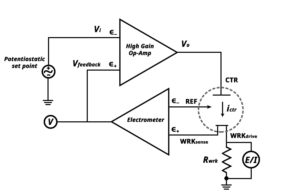
Let's start with reviewing the components in the potentiostat diagram above. Vi represents a user-controlled applied potential called the potentiostatic set point that is referenced to ground. Vi enters the inverting input (∈-) on the High Gain Op-Amp. The output (Vo) connects to the counter electrode lead (CTR). The reference electrode lead (REF) and the working sense lead (WRKsense) connect to a true difference amplifier called the electrometer. The output voltage (Vfeedback) from the electrometer feeds into a voltmeter (V) and into the non-inverting input (∈+) on the High Gain Op-Amp. The working electrode drive lead (WRKdrive) connects to a sense resistor (Rwrk) that connects to ground. The voltmeter (E/I), measures the potential across Rwrk, and converts it to a current. WRKsense and WRKdrive are shorted together and connect to the working electrode of interest. CTR, REF, WRKsense, and WRKdrive are all cables that come out of the potentiostat and connect to the electrochemical cell.
During potentiostat operation, the user applies a voltage Vi to the electrochemical cell. An output voltage, Vo, comes from the High Gain Op-Amp into the electrochemical cell through the counter electrode (CTR). The counter electrode passes current (ictr) through the solution to REF, WRKsense, and WRKdrive. Remember that the inputs to an operational amplifier have a high impedance, hence no current passes through them. Since the REF and WRKsense are connected to a high impedance operational amplifier, the only viable path for the current to flow is through WRKdrive.
The electrometer output voltage is the voltage difference between the REF and WRKsense. As the current travels between the CTR and WRKdrive,
the voltage drops across a gradient that is proportional to the bulk
solution resistance. This process affects the potential of REF and WRKsense. However, reference electrodes are designed to maintain a stable potential, and the potential at REF remains constant. This means that any measured changes in the potential come from WRKsense. The voltage difference between REF and WRKsense is the output voltage of the electrometer, Vfeedback. Vfeedback feeds into a voltmeter (V) to measure the difference between the REF and WRKsense. It also feeds into the non-inverting (∈+) input of the High Gain Op-Amp. Recall, that the High Gain Op-Amp amplifies the difference between ∈+ and ∈- (equation 1). If Vfeedback is not equal to Vi, the op-amp will either increase or decrease Vo until they are equal.
Finally, note that in the design of
the potentiostat, working electrode current is not directly measured.
Rather, the voltage is measured across Rwrk which is located between WRKdrive and ground. Rwrk is a known resistor, so based on the voltage measured across it, we can calculate the measured current via Ohm's Law.
(2)
Where i is the current, V is the voltage, and Rwrk is the known resistor between WRKdrive and ground. In summary, the current at the working electrode is measured by voltmeter (E/I) across Rwrk, the potential at the working electrode is measured by the electrometer (V),
and the applied potential is determined by the potentiostatic set
point. By utilizing the op-amp's feedback mechanism, the potential of
the working electrode with respect to the reference electrode can be
adjusted. Simultaneously adjusting potential while measuring the
current at the working electrode is the heart of voltammetry techniques.
The operational amplifier
and its feedback mechanism are critical for proper potential control of
the working electrode with respect to the reference electrode (in
controlled potential methods). Additional electronic components of a
potentiostat include a function generator, analog to digital (A/D)
converters, and digital to analog (D/A) converters.
Modern instrumentation routinely
translates between true analog responses and their digital equivalent.
Electrochemical experiments generate analog data (current and voltage),
data which are continuous and can take on any value. Computers require
digital data, represented with zeroes and ones. A/D converters rely
upon the instrumentation calibration to accurately translate analog
signals to digital signals. The opposite is true, that D/A converters
translate digital signals into continuous analog signals. In the case
of a potentiostat, current response (an analog signal) passes through an
A/D converter, where the computer is able to plot and manipulate data.
At the same time, digital waveforms generated by the computer pass
through a D/A converter, such that the waveform is applied as an analog
signal to the electrochemical cell.
Modern potentiostats include all
electronic components—op-amps, waveform generators, D/A and A/D
converters—in one instrument. In general, a researcher only requires a
potentiostat, which is often USB-interfaced with a computer equipped
with the potentiostat software. In summary, D/A and A/D converters
allow users to apply and measure potential and current values using a
computer.
In
electrochemistry, one of the parameters that can be measured is the so
called open circuit potential. This reading can have tremendous
significance and importance depending on the application. In this post,
we will dig deep into this versatile measurement and how to make the
most of it every time.
What is Open Circuit Potential?
In
a 3 electrode setup, the Open Circuit Potential, also known as OCP, is
the electrode potential that can be measured versus the reference
electrode when there is no current flowing through the working electrode
of an electrochemical system.
In general, however, it can be
simply referred to as the potential measured between two electrodes
immersed in an electrolyte when there is no current flowing.
What does the Open Circuit Potential represent?
The
OCP of an electrochemical system represents its thermodynamic
equilibrium. That is, the rates of oxidation and reduction are balanced.
What generates the Open Circuit Potential?
The
OCP occurs due to the charge separation at the electrode-electrolyte
interface. This charge separation occurs due to the difference in the
electrochemical activity between the electrode material and the
electrolyte.
What are the factors influencing the Open Circuit Potential?
There are mainly two factors that influence the resulting OCP: the electrode material and the electrolyte composition.
Influence of the Electrode Material on Open Circuit Potential
One of the most important factors that influence the OCP of an electrochemical system is the material of the electrodes.
Each
material has a different tendency to oxidize or reduce. This means that
each material has a different standard electrode potential, which has a
direct impact on the open circuit potential.
Influence of the Electrolyte Composition on Open Circuit Potential
The other most important factor in the OCP of an electrochemical system is electrolyte in contact with the electrodes.
The
different components that make up the electrolyte can affect the
standard electrode potential of the electrode materials. For example, pH
affects the OCP of carbon electrodes and ionic chloride concentration
affects the OCP of AgCl electrodes (thus the need for a fixed and known
concentration of KCl in reference electrodes) the Factors such as the
concentration of ionic species, pH and oxidation state of any redox
analytes, they all contribute to the measured OCP.
How do you measure Open Circuit Potential?
OCP is a very easy parameter to measure. In fact, while most research labs utilize potentiostats to measure OCP, in reality you only need a traditional voltmeter to measure it.
However, there are slight differences when measuring OCP with a potentiostat and a voltmeter. We explain it in detail below.
How to measure Open Circuit Potential with a potentiostat
When
using a potentiostat to measure OCP one must remember that, with this
instrument, all potentials are always measured versus the reference
electrode lead. So, from the 3 leads that most potentiostats have to
connect to electrochemical cells, you would only really need 2 of them:
So
to measure the OCP you would only need to connect the WE lead to the
electrode that you want to measure the OCP from and the RE to your
reference electrode in the system (often a Ag/AgCl electrode).
In
general, the counter electrode (CE) lead is not needed at all. Yet some
researchers may argue that having a 3rd counter electrode may help
obtain more stable readings.
In most cases, what scientists in the
lab would do when purely measuring OCP in an electrochemical system is
keep their measurement setup the same. So if a 3 electrode setup is
being used at the time, the lab operator would connect the potentiostat
in the same way they would connect it for any other electrochemical
measurement. This is useful because oftentimes an OCP measurement would
only be part of the characterisation experiments. So this approach
avoids having to rearrange the connections after the measurement.
How to measure Open Circuit Potential with a multimeter
While
most of our readers probably work with potentiostats, we think it is
interesting to know how to measure OCP with a digital multimeter too.
To measure OCP with a digital multimeter:
First
set your device in potential measurement mode. In most cases, this
would require turning the measurement knob to DC voltmeter mode and
selecting the appropriate potential range. However, always refer to the
user manual of your specific multimeter. For aqueous electrochemical
measurements, the best potential range would be in the Volts range, as
in most cases you would be measuring from a few mV up to 1.25 V.
Once
the multimeter is in voltmeter mode in the appropriate current range it
is time to connect to the respective electrodes. For this, connect the
black lead of the multimeter to the reference electrode and the red lead
to the working electrode. Please note that inverting these would invert
the measured potential.
How to interpret the Open Circuit Potential
OCP
is normally collected as a series of potential measurements during a
specific period of time, and it can be interpreted in multiple ways.
As
we explained above, OCP represents the equilibrium state of the
electrochemical system we are studying. Therefore, depending on the
application, the OCP reading can be transformed into actionable data.
(We will explain the applications of OCP in detail in the next section.)
For
now, let’s discuss the different ways that the OCP vs time curves can
present themselves: stable, erratic, noisy, drifting and evolving.
Stable Open Circuit Potential
Example of a stabe OCP signal. Acquired from 0.5 mM Methylene Blue in PBS on a gold PCB sensor.
A
stable OCP is characterized by a consistent and repeatable potential
value over time. This type of behaviour is normally achieved after some
time, once the electrodes have been in the electrolyte long enough that
any side reactions, such as those arising from electrode impurities or
double layer capacitance development, have terminated.
This type
of OCP behaviour is often a requirement in measurement protocols. For
example, in corrosion studies, electrodes are normally required to reach
a stable OCP before proceeding with the measurements.
OCP
stability in itself is a fuzzy term. Since most aqueous experiments are
prone to evaporation effects, and thus variations in electrolyte
composition, an OCP measurement may appear to be unstable if the
measurement is long enough. Yet in most cases, the OCP was stable, but
the system was changing.
To avoid such mistakes, OCP stability is
often determined using a certain stability criterion. This stability
criterion depends on the application, but it normally ranges in the mV/s
to the µV/s.
Erratic Open Circuit Potential
An
erratic OCP is characterized by quick (within a few seconds), high (few
hundreds of mVs) and often random (without any particular pattern)
variations of potential over time.
Such a behaviour is not common of electrochemical systems.
Therefore,
if you encounter such an OCP vs time curve, you likely have a
connection problem in your setup. In these cases, the best course of
action is to verify all the connections in your setup.
Noisy Open Circuit Potential
A
noisy OCP has a clear average value that varies slowly and according to
the conditions of the reactions at the electrode and/or electrolyte.
However, it has a superimposed disturbance that reduces the quality of
the data acquired.
While some level of noise is unavoidable, it is
best to try and keep it to a minimum and as close to the noise level of
the potentiostat instrument as possible.
There are two main types of noise that should be avoided: random and periodic.
Random Noise in Open Circuit Potential
Random
noise in OCP is characterized by sudden spikes in the signal. When it
is due to the noise level of the potentiostat, the data quality is
hardly affected and can be improved in post-processing using data
smoothing algorithms.
But when the data starts showing a lot of large spikes, then it is time to troubleshoot.
When large spikes in the OCP data appear consistently, it is a sign of 2 potential issues:
A faulty spring connection
Mechanical vibration
Nowadays most connections to SPEs
or electrochemical cells are performed with spring loaded connectors.
The most common are crocodile clips, edge connectors or pogo-pins.
These
types of connections suffer from wear and tear. And when the spring
starts to loose its elasticity, or the contact surfaces rust, it can
lead to a faulty connection. If this is the case, the best course of
action is to exchange them with a new connection.
With regards to
mechanical vibrations, these are normally less common. They may cause
connection issues by physically detaching the connections to the
electrochemical cell (thus exacerbating the effects of a spring
connector starting to fail) or by inducing significant movements of the
electrolyte. So, if the connections are working properly and you still
see a high noise level, look for vibrations. Vortexers and spinners are
common sources of mechanical vibrations in laboratories.
Periodic Noise in Open Circuit Potential
Periodic
Noise in OCP signals are characterized by a pattern that repeats over
time. In most cases, this noise is sinusoidal in nature.
This type
of noise is most of the times electronic. Especially if it matches the
frequency of the mains power, that is 50 or 60 Hz, depending on where
you are located. Moreover, this noise can also present itself as
harmonics of these frequencies.
In these case, there are two potential approaches to troubleshoot.
Adjust the datapoint acquisition rate to avoid picking up this noise
Filter out the noise signal in post-processing
If possible, it’s always best to remove the noise at the data acquisition stage.
One final potential source of periodic noise could be the connecting cables themselves.
Long
cables can effectively behave as an antenna, introducing noise into the
system. Most potentiostat manufacturers sell their connecting cables
with an electromagnetic shield to avoid this from happening. However, it
is common that glass reference electrodes, especially the economic
ones, do not have shielding on their connecting cable. As a result an
unsightly periodic noise is introduced in all measurements. In this
case, it is best to try to shield the cable, reduce its length, or
acquire a new glass reference electrode from a reputable manufacturer.
Drifting Open Circuit Potential
Example of a Drifting OCP. Acquired from a gold PCB sensor
coated with a polymer with entrapped methylene blue. This data shows a
ongoing increase in OCP as a result of changes within the polymer layer.
A
drifting OCP can be identified by a constant and slow slope that is not
related to environmental condition changes such as evaporation effects.
This slope can either be upwards or downwards. And it will persist even
when a change in the test conditions occurs. For example, when a
concentration of an analyte is changed as part of a measurement.
This drifting slope is normally a result of degradation of the electrode material and/or the formulation immobilized on top.
As materials attach, such as during biofouling, or dissolve, from an electrode, the measured OCP will change.
For
sensing applications, while not desired, a drifting OCP is an annoying
effect that has to be managed during data post-processing of one-off
short measurements. But for continuous and long measurements, it is a
sign that the device still requires more development. This is because
this degradation will eventually lead to the device no longer responding
to the target analyte.
Evolving Open Circuit Potential
Example of an evolving OCP. Acquired from 0.5 mM Methylene Blue in PBS upon adding a chemical reducer on a gold PCB sensor. The curve shows the chemical reduction of methylene blue to methylene white.
An evolving OCP is a curve that shows a variation in the signal as a result of an external stimulus.
This is the type of curve that is expected of active measurements, such as pH measurements and other ion selective electrodes.
These
types of OCP curves are normally characterized by an initial flat
region (baseline), an exponential increase region (when the external
stimulus is applied), and a final plateau (when the effect of the
external stimulus ends and the signal stabilize again).
Applications of Open Circuit Potential
OCP is a parameter of interest in multiple applications. Below we cover some of its most common applications.
Open Circuit Potential in Corrosion
In
corrosion science, electrochemistry can help determine corrosion rates
accurately and quickly compared to other, more conventional methods.
In
any electrochemical corrosion study, the first step is to determine the
OCP. In this application, the OCP relates to the corrosion potential of
the system and serves as a starting point for the characterisation of
corrosion.
Moreover, OCP in corrosion is also partly related to
the corrosion resistance of the electrode in a given electrolyte. With
higher OCP values being an indicative of higher corrosion resistance.
Open Circuit Potential in Sensing
OCP
is a common and desirable method for developing sensors. Since OCP
measurements arise from a type of potentiometry that drives no current,
this type of measurement has a low power consumption. This is why the
vast majority of potentiometric sensors operate with OCP.
While
there are some glucose sensors in the literature that work with OCP,
most commercial applications focus on ion sensing. Some of the most
common commercial ion selective electrodes (ISE) that operate in OCP
mode are the pH meter, sodium and potassium ISEs.
One particular application of OCP in sensing that is very common in analytical chemistry laboratories is titration.
While there are several types of titrations, most of them can be
monitored via OCP measurements using appropriate electrodes that, in
this application, are normally referred to as “titrodes”.
Open Circuit Potential in Electrochemical Energy Storage
OCP
has applications in electrochemical energy storage too. In batteries
and supercapacitors, the OCP, also referred to as Open Circuit Voltage
or OCV in this field, is an important parameter used to determine the
state of charge (SoC) of the device.
Therefore, OCP has two practical applications in energy storage:
Calibrating the cell to predict SoC by measuring the potential across
Determining self-discharge rates
Both of these applications are crucial for the development of energy storage devices.
The
first one enables manufacturers a quick and straightforward way to
measure charge percentage so that device developers can accurately
control battery charging.
And the second one allows researchers to
determine if the battery self-discharges too quickly and adjust the
design accordingly to mitigate this unwanted phenomena.
Pros and Cons of Open Circuit Potential Measurements
Pros
Cons
The equipment required to measure OCP is simple and economic.
Since
OCP is a passive measurement the acquired data has less features
compared to other electrochemical measurements such as voltammetry.
OCP measurements consume very low power.
Since OCP can change due to several factors, experimental conditions must be closely monitored.
OCP can easily be transformed into actionable information such as concentration of an analyte or a state of charge
Reliable OCP-based assays require either calibration, a special surface chemistry, or both.
Pros and Cons of OCP measurements
We
hope you have enjoyed our comprehensive post on Open Circuit Potential.
In this guide we have covered everything there is to know about OCP:
what it is, what influences it, how to measure it, and its real-world
applications. We have also looked into its pros and cons as an
electrochemical measurement. This way we expect that you will be able to
make an informed decision of whether this is a parameter of interest
for your investigation.
If you would like to know more about electrochemistry and its techniques, check our blog! We post regularly and have an extensive knowledge base.