Thanh navigation

Thứ Tư, 30 tháng 11, 2022

Arduino Variable Types

 Source: https://roboticsbackend.com/arduino-variable-types-complete-guide/#char

What are the different Arduino variable types?

Whether you are a complete Arduino beginner or you already know how to program, this guide will help you discover and all the most useful Arduino variable types.

First of all, Arduino is a subset of C/C++, with additional functionalities related to the hardware features of the board. So, you might expect to have similar data types. This is true for some types, but with Arduino you also get modified and new exclusive types.

Let’s discover all the Arduino variable types you will use, with the limits and particularities for each of them.

Table of Contents

Arduino Variable Types – Round Numbers

byte

The byte number is the smallest Arduino data type you can use for round numbers when programming with Arduino. A byte contains 8 bits.

A bit is simply a binary piece of information: 0 or 1.


You are learning how to use Arduino to build your own projects?

Check out Arduino For Beginners and learn step by step.


So, a byte will contain 8 binary values. For example, the number 45 written in 8-bit will look like this: 00101101. This is how the byte will be stored in the Arduino. In your program you can choose to either use the binary representation of the number, or the decimal representation (hexadecimal also works).

byte b = 260; // decimal
//... or ...
byte b = 0b00101101; // binary
// ... or ...
byte b = 0x2D; // hexadecimal

And you can print a number with the Serial.println() function, using different arguments for different representations of the number.

byte b = 45;
void setup() {
Serial.begin(9600);
Serial.println(b); // print in decimal by default
Serial.println(b, DEC); // print in decimal, same as above
Serial.println(b, BIN); // print in binary
Serial.println(b, HEX); // print in hexadecimal
}
void loop() {
}

Here the result in the Serial Monitor will be:

45
45
101101
2D

The min value for a byte is 0, and the max value is 255 (byte is an unsigned data type, more on that later in this tutorial).

As you can see that’s quite short, so pay attention when you use this data type. Only use it to store very small numbers.

And what happens if you try to store a number lower than 0, or bigger than 255? Well the program will still work, but your variable will overflow. Overflow means that once the value reaches 256, it will go back to 0.

So, if you try to assign 260 to a byte:

byte b = 260;
void setup() {
Serial.begin(9600);
Serial.println(b); // print in decimal by default
Serial.println(b, DEC); // print in decimal, same as above
Serial.println(b, BIN); // print in binary
Serial.println(b, HEX); // print in hexadecimal
}
void loop() {
}

You will get:

4
4
00000100
4

260 has become 4, because 256 goes back to 0, then 257 becomes 1, etc… and 260 becomes 4.

So, again, pay attention when using small data types such as byte in your Arduino programs: if you try to use a too big number, the variable will overflow and its value won’t be correct. Your program will still compile, but when running you’ll get all kinds of application errors.

Int

Int, or integer, is one of the most common variable types you will use and encounter.

An int is a round number which can be positive or negative.

On Arduino boards such as Uno, Nano, and Mega, an int stores 2 bytes of information. So, for example, 9999 will be represented by 00100111 00001111. Although you don’t need to know the binary representation, you can just work with decimal numbers.

int i = 9999;
int j = -4578;

You can use int everywhere, to store any information represented by a round number. For example: a counter, temperature, number of steps for a stepper motor, angle for a servomotor, etc.

The min value for a 2-bytes int is -32 768 and the max value is +32 767. As for bytes, it can overflow.

For example, if you try to assign 32 768 (which is just above the max limit), the value you will read inside the variable will be -32 768.

And if you try to assign -32 769, you will get +32 767.

Thus, pay attention not to use too big numbers with int. On boards such as Arduino Due and Zero, integers store 4 bytes, so the value range is much higher: -2,147,483,648 to 2,147,483,647.

But on classic Arduino boards (Uno, Nano, Mega, etc.), if you want to use bigger integer numbers you’ll have to use long instead of int.

long

A long is exactly the same as an int, but using 4 bytes. The minimum value becomes -2,147,483,648 and the max value 2,147,483,647. With this you don’t need to worry too much about overflowing.

long l = 4000000;
long k = - 1234567;

Usually, you’ll use long when you know (or suppose) the size of an int won’t be enough.

Arduino Variable Types – unsigned

For the standard round number variables, you can add “unsigned” before the data type to modify it a little bit.

If you add “unsigned”, the variable will contain only positive numbers, starting from 0.

This is what we had for byte, which is already an unsigned data type (in fact, similar to unsigned char, which you’ll see later).

unsigned int

To create an unsigned int:

unsigned int a = 45000;

An unsigned int will start at 0 and have a max value of 65 535 (4,294,967,295 in 4 bytes board such as Due/Zero). As you don’t have negative numbers anymore, all those numbers are added to the max positive value you can use.

The concept of overflow here is the same. If you try to use 65 536 you’ll go back to 0.

So, unsigned int can be used if you’re sure that you’ll only store positive numbers (it will enforce it) for the variable. Also, the max limit increases, so for example if you have to use a variable that goes from 0 until 50 000 for reading a sensor, this will be a good option.

unsigned long

To create an unsigned long:

unsigned long b = 999999;

An unsigned long will start at 0 and have a max value of 4,294,967,295, which is a very big number.

Again, the use you’ll make of long is pretty similar to int data type, just for larger numbers.

On Arduino, when you try to get the time with millis or micros, you will get a result in unsigned long.

Arduino Variable Types – bool/boolean

The bool/boolean is a particular Arduino data type which only contains a binary information: 1 or 0 (true or false).

You will use booleans to test conditions where the answer is a simple yes/no.

bool isComponentAlive = false;
void setup() {
if (!componentAlive)
{
// start initialization process
isComponenetAlive = true;
}
}
void loop() {
}

In Arduino you can use the standard C++ bool type, or the boolean type which is identical. However, the Arduino documentation suggests that you only use bool.

Arduino Variable Types – Float Numbers

For now we’ve only seen how to store and use round numbers with Arduino. But what if you want to store a number such as 3.14 ?

float

A float variable can store a negative or positive float number. As for every data type it has a minimum and a maximum: 3.4028235E+38 to -3.4028235E+38. This is much bigger than long, even though a float is also stored on 4 bytes. The reason is simply because both data types are stored in a different manner.

To create a float:

float f = 2.97;
float g = -6000.0;

So, the resolution of a float is greater than round numbers, which make them convenient for some computations or to read a continuous value from a sensor.

Note however that the precision for float is not 100%, contrary to round number data types.

For example, if you try to assign 3.00 inside a float number, the real value might be something like 3.0000001.

double

In boards such as Uno, Mega and Nano, double and float are identical.

On Due for example, the double is stored on 8 bytes instead of 4, which makes it different. You can store even bigger numbers.

One thing to know about float numbers (float or double data type): the Arduino micro-controller will take much more time to process a computation with float numbers than with round numbers. As the computation power is very limited, try to use round numbers as much as you can, and float numbers only when you don’t have the choice.

Arduino Variable Types – Text data types

Great, now you have seen how to store booleans, round and float numbers. The last important category here is how to store text, which is often used when you want to share information with the user (text makes more sense to a human than a hexadecimal code) or to communicate in ASCII for example.

char

The char data type is quite particular because it’s mainly used to store letters, but in the end the real value is a number between -128 and +127 (stored in 1 byte). The corresponding values between letter and numbers are the ones you can find in the ASCII table.

For example, the letter ‘F’ uppercase has the value 70, and ‘f’ lowercase has the value 102.

char f_upper = 'F';
// OR - same as
char f_upper = 70;
char f_lower = 'f';
// OR - same as
char f_lower = 102;

You can make computations using char. If you add +1 to the letter ‘F’, the number will become 71, and the corresponding letter ‘G’ uppercase.

The char data type can be quite useful to send data over Serial/I2C/SPI between devices. It doesn’t take much space (1 byte which is the minimum), so it’s faster to transfer, and you can directly associate an action to a letter – ex: ‘m’ to move the motor, ‘s’ to stop, ‘a’ to accelerate, etc.

unsigned char

The unsigned char data type is in fact the exact same as the byte variable type. Both have a minimum value of 0 and a max of 255.

It is recommended that you use byte instead of unsigned char.

String

The String data type is specific to Arduino, you can’t find it in standard C/C++. Also, note the uppercase “S”. The variable type is String, not string.

You will use this type to store text. You can perform operations such as concatenation directly with the “+” operator.

String a = "Hello";
String b = "world";
String result = a + " " + b;

String is a class, it’s not a primitive data type. To create a string, you’d have to use an array of chars. With the String class, you get to simplify your life and you also have a bunch of extra functionalities.

Array of Variables

And of course, each of the Arduino data types you’ve seen here can be stored inside an array.

Make sure to only use one single data type for all elements of an array.

int intArray[3] = { 1, -2, 3 };
long longArray[3] = {4500, -798, 0};
unsigned int unsignedIntArray[3] = { 10, 11, 12 };
unsigned long unsignedLongArray[3] = {20000, 30000, 999999};
bool boolArray[3] = { false, true, false };
double floatArray[3] = { 8.0, 9.9, 12121313131.3 };
double doubleArray[3] = { 3.14, -3.14, 7.00 };
char charArray[3] = { 'a', 'b', 'c' }; // or directly: = "abc";
String stringArray[3] = { "Hello", " ", "World" };

Conclusion – Arduino Data Types

In this tutorial you have discovered all the standard Arduino data types you’ll most frequently use in your programs.

Don’t hesitate to come back to this guide whenever you’re not sure about which variable type you should use, or what are their limitations.

A few general pieces of advice to finish:

  • As you saw, you could get erratic results if some of your variables overflow. So make sure to always now what is the range and the min/max value a variable can store.
  • Also, the more complex the data type, the more computation time it will take. And the Arduino is much less powerful than a “standard” computer, so you’ll have to take that into account. If you see that your program is too slow, then you might want to measure how long a certain action takes, and try to make it faster by changing the data types for some variables and rearranging/optimizing the operations.
  • Finally, if you’re using round numbers and you know that you only expect positive numbers, use the unsigned version of the data type. Your program will be clearer and less prone to errors.

Now, don’t forget that premature optimization is the root of all evil. When you write your programs, use larger data type if any hesitation, and only optimize when you see that things are too slow.
Interrupt In Arduino


What is an Interrupt pin?

 A real life analogy

Example 1

Let’s use a real life analogy. Imagine you’re waiting for an important email. You don’t know when it will arrive, but you want to make sure you read it as soon as it arrives in your mailbox.

The most basic solution is to frequently check your mailbox – let’s say, every 5 minutes – so you’re sure the maximum delay between the reception of the email, and you reading it, is 5 minutes. But this is really not an ideal solution. First, you’ll spend all your time refreshing your mailbox and won’t do any productive thing in the meantime. And second, this is relatively inefficient. When the email arrives, you’ll have up to 5 minutes delay before you read it.

This technique is called “polling“. At a given frequency, you’re polling the state of something to see if a new information arrived. At a human scale you see that it’s completely not worth it.

The other possible way to do that is to use interrupts. For us humans, this means turning on notifications. As soon as the email has arrived, you will get a popup on your phone/computer saying that the email is here. You can now check your email, and the delay between the reception and you reading the email is basically zero.

Let’s add more details to this analogy: the email you’re about to receive contains a special offer to get a discount on a given website – and this offer is available only for 2 minutes. If you use the “polling” technique, there is a chance that you miss some data (in this example, you’ll miss the discount). With interrupts, you can be sure you won’t miss it.

Example 2

Another example: you’re waiting to talk to the postman about something. You now he will arrive between 9am and 11am. First option – polling – you can keep going to your door to check if he has arrived. But maybe you’ll miss him, because you can’t always be at your window looking at the street.

Second option – interrupts – you put a note on your door saying “Dear Mr. Postman, please ring the bell when you see this”. As soon as the postman arrives, he will ring the bell and you won’t miss him.

In both scenarios, you stop your current action. That’s why it’s called an interruption. You have to stop what you’re doing to handle the interruption, and only after you’re done with it, you can resume your action.

Interrupts on Arduino

Arduino Interrupts work in a similar way.

For example, if you are waiting for a user to press on a push button, you can either monitor the button at a high frequency, or use interrupts. With interrupts, you’re sure that you won’t miss the trigger.

The monitoring for Arduino Interrupts is done by hardware, not software. As soon as the push button is pressed, the hardware signal on the pin triggers a function inside the Arduino code. This stops the mains execution of your program. After the triggered function is done, the main execution resumes.

Note that for the real life analogies above, interrupts make much more sense than the polling technique. However I want to point that sometimes, polling can be a better choice. At human scale, interrupts make much more sense. At a micro-controller scale, where the frequency of execution is much higher, sometimes it becomes complicated than that and the choice is not always obvious. We’ll discuss more about it later in this post.

Arduino Interrupts Pins

Arduino Interrupts Pins are using digital pins. However, usually you can’t use all available digital pins. Only some of them have the functionality enabled.

Here are the pins you can use for interrupts on the main Arduino boards:

Arduino Board Digital Pins for Interrupts
Arduino Uno, Nano, Mini 2, 3
Arduino Mega 2, 3, 18, 19, 20, 21
Arduino Micro, Leonardo 0, 1, 2, 3, 7
Arduino Zero All digital pins except 4
Arduino Due All digital pins

On this tutorial we’ll be using an Arduino Uno board, so we only have two choices! We can either use pin 2 or pin 3.

If you want to use more interrupts in your programs, you can switch to the Arduino Mega. This board is really pretty close from the Arduino Uno, with more pins. And if you need even more interrupts, choose something like the Arduino Due – pay attention though, the Due works with 3.3V, not 5V.

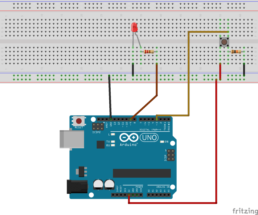
Arduino Schematics - Button on Interrupt pin and LED

Note that we are using the pin 3 for the button. As previously stated, on Arduino Uno you can only use pin 2 and 3 for interrupts. Pay attention when you have to choose a pin for an interrupt. If the pin is not compatible with interrupts your program won’t work (but still compile), and you’ll spend quite some time scratching your head while trying to find a solution.


Types of interrupts

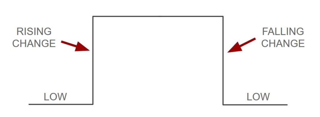
Arduino interrupts are triggered when there is a change in the digital signal you want to monitor. But you can choose exactly what you want to monitor. For that you’ll have to modify the 3rd parameter of the attachInterrupt() function:

  • RISING: Interrupt will be triggered when the signal goes from LOW to HIGH
  • FALLING: Interrupt will be triggered when the signal goes from HIGH to LOW
  • CHANGE: Interrupt will be triggered when the signal changes (LOW to HIGH or HIGH to LOW)
  • LOW: Interrupt will be triggered whenever the signal is LOW

Arduino Interrupt Mode

Practically speaking, you could monitor when the user presses the buttons, or when he/she releases the button, or both.

If you’ve added a pull-down resistor to the button – meaning its normal state is LOW – then monitoring when it’s pressed means you have to use RISING. If you’ve added a pull-up resistor, the button state is already HIGH, and you have to use FALLING to monitor when it’s pressed (linked to the ground).

Arduino code without interrupts

#define LED_PIN 9
#define BUTTON_PIN 3
byte ledState = LOW;
void setup() {
pinMode(LED_PIN, OUTPUT);
pinMode(BUTTON_PIN, INPUT);
}
void loop() {
if (digitalRead(BUTTON_PIN), HIGH) {
ledState = !ledState;
}
digitalWrite(LED_PIN, ledState);
}

Nothing really new here. We initialize the pin of the LED as OUTPUT and the pin of the button as INPUT. In the loop() we monitor the button state and modify the LED state accordingly. Note that for simplicity I haven’t use a debounce on the button.

Arduino code with interrupts

#define LED_PIN 9
#define BUTTON_PIN 3
volatile byte ledState = LOW;
void setup() {
pinMode(LED_PIN, OUTPUT);
pinMode(BUTTON_PIN, INPUT);
attachInterrupt(digitalPinToInterrupt(BUTTON_PIN), blinkLed, RISING);
}
void loop() {
// nothing here!
}
void blinkLed() {
ledState = !ledState;
digitalWrite(LED_PIN, ledState);
}

Here we changed the way we are monitoring the push button. Instead of polling its state, there is now an interrupt function attached to the pin. When the signal on the button pin is rising – which means it’s going from LOW to HIGH, the current program execution – loop() function – will be stopped and the blinkLed() function will be called. Once blinkLed() has finished, the loop() can continue.

Here, the main advantage you get is that there is no more polling for the button in the loop() function. As soon as the button is pressed, blinkLed() will be called, and you don’t need to worry about it in the loop().

As you might have noticed, we use the keyword “volatile” in front of the ledState variable. I’ll explain you later in this post why we need that.

You have to use the attachInterrupt() function to attach a function to an interrupt pin. This function takes 3 parameters: the interrupt pin, the function to call, and the type of interrupt.

Five things you need to know about Arduino Interrupts

1. Keep the interrupts fast

As you can guess, you should make the interrupt function as fast as possible, because it stops the main execution of your program. You can’t do heavy computation. Also, only one interrupt can be handled at a time.

What I recommend you to do is to only change state variables inside interrupt functions. In the main loop(), you check for those state variables and do any required computation or action.

Let’s say you want to move a motor, and this action is triggered by an interrupt. In this case, you could have a variable named “shouldMoveMotor” that you set to “true” in the interrupt function.

In your main program, you check for the state of the “shouldMoveMotor”. When it’s true, you start moving the motor.

#define BUTTON_PIN 3
volatile bool shouldMoveMotor = false;
void setup() {
pinMode(BUTTON_PIN, INPUT);
attachInterrupt(digitalPinToInterrupt(BUTTON_PIN), triggerMoveMotor, RISING);
}
void loop() {
if (shouldMoveMotor) {
shouldMoveMotor = false;
moveMotor();
}
}
void triggerMoveMotor() {
shouldMoveMotor = true;
}
void moveMotor() {
// this function may contains code that
// requires heavy computation, or takes
// a long time to execute
}

And you can do exactly the same for a heavy computation, for example if the computation takes more than a few microseconds to complete.

If you don’t keep the interrupts fast, you might miss important deadlines in your code. For a mobile robot with 2 wheels, that may make the motor movement jerky. For communication between devices, you might miss some data, etc.

When you need to deal with real-time constraints, this rule becomes even more important.

2. Time functionalities and interrupts

A basic rule of thumb: don’t use time functionalities in your interrupts. Here’s more details about the 4 main time functions:

  • millis(): this will return the time spent since the Arduino program has started, in milliseconds. This function relies on some other interrupts to count, and as you are inside an interrupt, other interrupts are not running. Thus, if you use millis(), you’ll get the last stored value, which will be correct, but when inside the interrupt function, the millis() value will never increase.
  • delay(): this one will simply not work, as it also relies on interrupts. Plus, even if it was possible, you should not use it because you now know that you have to keep the interrupts very fast.
  • micros(): this function is the same as millis(), but returns the time in microseconds. However, contrary to millis(), micros() will work at the beginning of an interrupt. But after 1 or 2 milliseconds, the behavior won’t be accurate and you may have a permanent drift every time you use micros() afterwards. Again, the advice is the same: make your interrupts short and fast!
  • delayMicroseconds(): this one will work as usual, but… Don’t use it. As you saw before, there are too many things that can go wrong if you stay too long in an interrupt.

All in all, you should avoid using those functions.

Maybe using millis() or micros() can sometimes be useful, if you want to make a comparison of duration (for example to debounce a button). But you can also do that in your code, using the interrupt only to notify of a change in the state of the monitored signal.

3. Don’t use the Serial library inside interrupts

The Serial library is very useful to debug and communicate between your Arduino board and another board or device. But it’s not a great fit for interrupt functions.

When you are inside an interrupt, the received Serial data may be lost. Thus it’s not a good idea to use the reading functionalities of Serial. Also if you make the interrupt too long, and read from Serial after that in your main code, you may still have lost some parts of the data.

You can use Serial.print() inside an interrupt for debugging, for example if you’re not sure when the interrupt is triggered. But it also has its own source of problems.

The best way to print something from an interrupt, is simply to set a flag inside the interrupt, and poll this flag inside the main loop() program. When the flag is turned on, you print something, and turn off the flag. Doing that will save you from potential headaches.

4. Volatile variables

If you modify a variable inside an interrupt, then you should declare this variable as volatile.

The compiler does many things to optimize the code and the speed of the program. This is a good thing, but here we need to tell it to “slow down” on optimization.

For example, if the compiler sees a variable declaration, but the variable is not used anywhere in the code (except from interrupts), it may remove that variable. With a volatile variable you’re sure that it won’t happen, the variable will be stored anyway.

Also, when you use volatile it tells the controller to reload the variable whenever it’s referenced. Sometimes the compiler will use copies of variables to go faster. Here you want to make sure that every time you access/modify the variable, either in the main program or inside an interrupt, you get the real variable and not a copy.

Note that only variables that are used inside and outside an interrupt should be declared as volatile. You don’t want to unnecessarily slow down your code.

5. Interrupts parameters and returned value

An interrupt function can’t take any parameter, and it doesn’t return any value. Basically if you had to write a prototype for an interrupt this would be something like

void interruptFunction();
.

Thus, the only way to share data with the main program is through global volatile variables. In an interrupt you can also get and set data from hardware pins, as long as you keep the program short. For example, using digitalRead() or digitalWrite() may be OK if you don’t abuse it.

Conclusion

Arduino interrupts are very useful when you want to make sure you don’t miss any change in a signal you monitor (on a digital pin mostly).

However, during this post you saw that there are many rules and limitations when using interrupts. This is something you should handle with care, and not use too much. Sometimes, using simple polling may be more appropriate, if for example you manage to write an efficient and deterministic multitasking Arduino program.

Interrupts can also be used just to trigger a flag, and you keep using the polling technique inside your main loop() – but this time, instead of monitoring the hardware pin, you monitor the software flag.

The main takeaway for you, if you want to use interrupts in your code: keep your interrupts short. Thus you will avoid many unnecessary and hard-to-debug problems.

Source: https://roboticsbackend.com/arduino-interrupts/#Types_of_interrupts


Thứ Sáu, 25 tháng 11, 2022

Timer/Counter

http://arduino.vn/bai-viet/411-timercounter-tren-avrarduino

http://www.hocavr.com/2018/06/c-cho-avr.html

https://www.digikey.com/en/maker/blogs/2022/how-to-avoid-using-the-delay-function-in-arduino-sketches

https://www.hobbytronics.co.uk/arduino-timer-interrupts


Thứ Tư, 16 tháng 11, 2022

1-Wire protocol

https://www.maximintegrated.com/en/design/technical-documents/app-notes/1/126.html

 https://www.maximintegrated.com/en/design/technical-documents/app-notes/1/162.html

https://embedded-lab.com/blog/exploring-stc-8051-microcontrollers-coding/32/

Thứ Tư, 9 tháng 11, 2022

RTC - DS1307/DS3231


I. Chip DS1307.
     DS1307 là chip đồng hồ thời gian thực (RTC : Real-time clock), khái niệm thời gian thực ở đây được dùng với ý nghĩa thời gian tuyệt đối mà con người đang sử dụng, tình bằng giây, phút, giờ…DS1307 là một sản phẩm của Dallas Semiconductor (một công ty thuộc Maxim Integrated Products). Chip này có 7 thanh ghi 8-bit chứa thời gian là: giây, phút, giờ, thứ (trong tuần), ngày, tháng, năm. Ngoài ra DS1307 còn có 1 thanh ghi điều khiển ngõ ra phụ và 56 thanh ghi trống có thể dùng như RAM. DS1307 được đọc và ghi thông qua giao diện nối tiếp I2C (TWI của AVR) nên cấu tạo bên ngoài rất đơn giản. DS1307 xuất hiện ở 2 gói SOIC và DIP có 8 chân như trong hình 1.

Hình 1. Hai gói cấu tạo chip DS1307.
       Các chân của DS1307 được mô tả như sau:
       - X1 và X2: là 2 ngõ kết nối với 1 thạch anh 32.768KHz làm nguồn tạo dao động cho chip.
       - VBAT: cực dương của một nguồn pin 3V nuôi chip.
       - GND: chân mass chung cho cả pin 3V và Vcc.
       - Vcc: nguồn cho giao diện I2C, thường là 5V và dùng chung với vi điều khiển. Chú ý là nếu Vcc không được cấp nguồn nhưng VBAT được cấp thì DS1307 vẫn đang hoạt động (nhưng không ghi và đọc được).
       - SQW/OUT: một ngõ phụ tạo xung vuông (Square Wave / Output Driver), tần số của xung được tạo có thể được lập trình. Như vậy chân này hầu như không liên quan đến chức năng của DS1307 là đồng hồ thời gian thực, chúng ta sẽ bỏ trống chân này khi nối mạch.
       - SCL và SDA là 2 đường giao xung nhịp và dữ liệu của giao diện I2C mà chúng ta đã tìm hiểu trong bài TWI của AVR.
Có thể kết nối DS1307 bằng một mạch điện đơn giản như trong hình 2.
Hình 2. Mạch ứng dụng đơn giản của DS1307.
      Cấu tạo bên trong DS1307 bao gồm một số thành phần như mạch nguồn, mạch dao động, mạch điều khiển logic, mạch giao điện I2C, con trỏ địa chỉ và các thanh ghi (hay RAM). Do đa số các thành phần bên trong DS1307 là thành phần “cứng” nên chúng ta không có quá nhiều việc khi sử dụng DS1307. Sử dụng DS1307 chủ yếu là ghi và đọc các thanh ghi của chip này. Vì thế cần hiểu rõ 2 vấn đề cơ bản đó là cấu trúc các thanh ghi và cách truy xuất các thanh ghi này thông qua giao diện I2C. Phần này chúng ta tìm hiểu cấu trúc các thanh ghi trước và cách truy xuất chúng sẽ tìm hiểu trong phần 2, điều khiển DS1307 bằng AVR.
       Như tôi đã trình bày, bộ nhớ DS1307 có tất cả 64 thanh ghi 8-bit được đánh địa chỉ từ 0 đến 63 (từ 0x00 đến 0x3F theo hệ hexadecimal). Tuy nhiên, thực chất chỉ có 8 thanh ghi đầu là dùng cho chức năng “đồng hồ” (tôi sẽ gọi là RTC) còn lại 56 thanh ghi bỏ trông có thể được dùng chứa biến tạm như RAM nếu muốn. Bảy thanh ghi đầu tiên chứa thông tin về thời gian của đồng hồ bao gồm: giây (SECONDS), phút (MINUETS), giờ (HOURS), thứ (DAY), ngày (DATE), tháng (MONTH) và năm (YEAR). Việc ghi giá trị vào 7 thanh ghi này tương đương với việc “cài đặt” thời gian khởi động cho RTC. Việc đọc giá từ 7 thanh ghi là đọc thời gian thực mà chip tạo ra. Ví dụ, lúc khởi động chương trình, chúng ta ghi vào thanh ghi “giây” giá trị 42, sau đó 12s chúng ta đọc thanh ghi này, chúng ta thu được giá trị 54. Thanh ghi thứ 8 (CONTROL) là thanh ghi điều khiển xung ngõ ra SQW/OUT (chân 6). Tuy nhiên, do chúng ta không dùng chân SQW/OUT nên có thề bỏ qua thanh ghi thứ 8. Tổ chức bộ nhớ của DS1307 được trình bày trong hình 3.
Hình 3. Tổ chức bộ nhớ của DS1307.
      Vì 7 thanh ghi đầu tiên là quan trọng nhất trong hoạt động của DS1307, chúng ta sẽ khảo sát các thanh ghi này một cách chi tiết. Trước hết hãy quan sát tổ chức theo từng bit của các thanh ghi này như trong hình 4.
Hình 4. Tổ chức các thanh ghi thời gian.
      Điều đầu tiên cần chú ý là giá trị thời gian lưu trong các thanh ghi theo dạng BCD. BCD là viết tắt của cụm từ Binary-Coded Decimal, tạm dịch là các số thập phân theo mã nhị phân. Ví dụ bạn muốn cài đặt cho thanh ghi MINUTES giá trị 42. Nếu quy đổi 42 sang mã thập lục phân thì chúng ta thu được 42=0x2A. Theo cách hiểu thông thường chúng ta chỉ cần gán MINUTES=42 hoặc MINUTES=0x2A, tuy nhiên vì các thanh ghi này chứa giá trị BCD nên mọi chuyện sẽ khác, tôi sẽ diễn giải bằng hình 5.
Hình 5. Số BCD.
      Với số 42, trước hết nó được tách thành 2 chữ số (digit) 4 và 2. Mỗi chữ số sau đó được đổi sang mã nhị phân 4-bit. Chữ số 4 được đổi sang mã nhị phân 4-bit là 0100 trong khi 2 được đổi thành 0010. Ghép mã nhị phân của 2 chữ số lại chúng ta thu được mốt số 8 bit, đó là số BCD. Với trường hợp này, số BCD thu được là 01000010 (nhị phân) = 66. Như vậy, để đặt số phút 42 cho DS1307 chúng ta cần ghi vào thanh ghi MINUTES giá trị 66 (mã BCD của 42). Tất cả các phần mềm lập trình hay thanh ghi của chip điều khiển đều sử dụng mã nhị phân thông thường, không phải mã BCD, do đó chúng ta cần viết các chương trình con để quy đổi từ số thập nhị phân (hoặc thập phân thường) sang BCD, phần này sẽ được trình bày trong lúc lập trình giao tiếp với DS1307. Thoạt nhìn, mọi người đều cho rằng số BCD chỉ làm vấn đền thêm rắc rối, tuy nhiên số BCD rất có ưu điểm trong việc hiển thị nhất là khi hiển thị từng chữ số như hiển thị bằng LED 7 đoạn chẳng hạn. Quay lại ví dụ 42 phút, giả sử chúng ta dùng 2 LED 7-đoạn để hiện thị 2 chữ số của số phút. Khi đọc thanh ghi MINUTES chúng ta thu được giá trị 66 (mã BCD của 42), do 66=01000010 (nhị phân), để hiển thị chúng ta chỉ cần dùng phương pháp tách bit thông thường để tách số 01000010 thành 2 nhóm 0100 và 0010 (tách bằng toán tử shift “>>” của C hoặc instruction LSL, LSR trong asm) và xuất trực tiếp 2 nhóm này ra LED vì 0100 = 4 và 0010 =2, rất nhanh chóng. Thậm chí, nếu chúng ta nối 2 LED 7-đoạn trong cùng 1 PORT, việc tách ra từng digit là không cần thiết, để hiển thị cả số, chỉ cần xuất trực tiếp ra PORT. Như vậy, với số BCD, việc tách và hiển thị digit được thực hiện rất dễ dàng, không cần thực hiện phép chia (rất tốn thời gian thực thi) cho cơ số 10, 100, 1000…như trong trường hợp số thập phân.
     Thanh ghi giây (SECONDS): thanh ghi này là thanh ghi đầu tiên trong bộ nhớ của DS1307, địa chỉ của nó là 0x00. Bốn bit thấp của thanh ghi này chứa mã BCD 4-bit của chữ số hàng đơn vị của giá trị giây. Do giá trị cao nhất của chữ số hàng chục là 5 (không có giây 60 !) nên chỉ cần 3 bit (các bit SECONDS6:4) là có thể mã hóa được (số 5 =101, 3 bit). Bit cao nhất, bit 7, trong thanh ghi này là 1 điều khiển có tên CH (Clock halt – treo đồng hồ), nếu bit này được set bằng 1 bộ dao động trong chip bị vô hiệu hóa, đồng hồ không hoạt động. Vì vậy, nhất thiết phải reset bit này xuống 0 ngay từ đầu.
     Thanh ghi phút (MINUTES): có địa chỉ 0x01, chứa giá trị phút của đồng hồ. Tương tự thanh ghi SECONDS, chỉ có 7 bit của thanh ghi này được dùng lưu mã BCD của phút, bit 7 luôn luôn bằng 0.
      Thanh ghi giờ (HOURS): có thể nói đây là thanh ghi phức tạp nhất trong DS1307. Thanh ghi này có địa chỉ 0x02. Trước hết 4-bits thấp của thanh ghi này được dùng cho chữ số hàng đơn vị của giờ. Do DS1307 hỗ trợ 2 loại hệ thống hiển thị giờ (gọi là mode) là 12h (1h đến 12h) và 24h (1h đến 24h) giờ, bit6 (màu green trong hình 4) xác lập hệ thống giờ. Nếu bit6=0 thì hệ thống 24h được chọn, khi đó 2 bit cao 5 và 4 dùng mã hóa chữ số hàng chục của giá trị giờ. Do giá trị lớn nhất của chữ số hàng chục trong trường hợp này là 2 (=10, nhị phân) nên 2 bit 5 và 4 là đủ để mã hóa. Nếu bit6=1 thì hệ thống 12h được chọn, với trường hợp này chỉ có bit 4 dùng mã hóa chữ số hàng chục của giờ, bit 5 (màu orangetrong hình 4) chỉ buổi trong ngày, AM hoặc PM. Bit5 =0 là AM và bit5=1 là PM. Bit 7 luôn bằng 0. (thiết kế này hơi dở, nếu dời hẳn 2 bit mode và A-P sang 2 bit 7 và 6 thì sẽ đơn giản hơn).
     Thanh ghi thứ (DAY – ngày trong tuần): nằm ở địa chĩ 0x03. Thanh ghi DAY chỉ mang giá trị từ 1 đến 7 tương ứng từ Chủ nhật đến thứ 7 trong 1 tuần. Vì thế, chỉ có 3 bit thấp trong thanh ghi này có nghĩa.
     Các thanh ghi còn lại có cấu trúc tương tự, DATE chứa ngày trong tháng (1 đến 31), MONTH chứa tháng (1 đến 12) và YEAR chứa năm (00 đến 99). Chú ý, DS1307 chỉ dùng cho 100 năm, nên giá trị năm chỉ có 2 chữ số, phần đầu của năm do người dùng tự thêm vào (ví dụ 20xx).
      Ngoài các thanh ghi trong bộ nhớ, DS1307 còn có một thanh ghi khác nằm riêng gọi là con trỏ địa chỉ hay thanh ghi địa chỉ (Address Register). Giá trị của thanh ghi này là địa chỉ của thanh ghi trong bộ nhớ mà người dùng muốn truy cập. Giá trị của thanh ghi địa chỉ (tức địa chỉ của bộ nhớ) được set trong lệnh Write mà chúng ta sẽ khảo sát trong phần tiếp theo, AVR và DS1307. Thanh ghi địa chỉ được tôi tô đỏ trong hình 6, cấu trúc DS1307.
Hình 6. Cấu trúc DS1307.
 II. AVR và DS1307.
      Phần này tôi hướng dẫn lập trình điều khiển và giao tiếp với DS1307 bằng AVR, dùng WinAVR. Do DS1307 hoạt động như một Slave I2C, bạn nhất thiết phải đọc lại “Bài 8 -  Giao tiếp TWI-I2C”, nhất là là 2 chế độ Master (Send và Reveive). Tôi sẽ không đề cập lại toàn bộ giao diện I2C nhưng tóm tắt cách thực hiện với AVR như sau: để thực hiện cuộc gọi ở chế độ Master, AVR sẽ gởi điều kiện START, tiếp theo là 7 bit địa chỉ Slave (SLA) +1 bit Write/Read, kế đến là quá trình đọc hay ghi dữ liệu giữa Master và Slave bằng các byte dữ liệu 8 bit (có thể chỉ 1 byte hoặc 1 dãy bytes), cứ sau mỗi byte sẽ có 1 bit ACK hoặc NOT ACK. Cuộc gọi kết thúc với việc Master phát điều kiện STOP. Cứ mỗi một quá trình, sẽ có 1 “code” được sinh ra trong thanh ghi trạng thái TWSR, kiểm tra giá trị code này để biết quá trình giao tiếp có thành công không. Bạn cần nhơ dãy code thành công khi Master truyền dữ liệu là: 0x08 -> 0x18 -> 0x28 ->…->0x28. Và dãy code thành công khi Master truyền dữ liệu là 0x08 - > 0x40 - > 0x50 ->…->0x50 -> 0x58. Nắm được cách  ghi và đọc của AVR Master là bạn đã nắm được 50% cách giao tiếp với DS1307, 50% còn lại chúng ta phải hiểu cách bố trí dãy dữ liệu của riêng DS1307. Hãy theo dõi phần tiếp theo..
      Vì DS1307 là một Slave I2C nên chỉ có 2 mode (chế độ) hoạt động giao tiếp với chip này. Hai mode của DS1307 bao gồm Data Write (từ AVR đến DS14307) và Data Read (từ DS1307 vào AVR). Mode Data Write được dùng khi xác lập giá trị ban đầu cho các thanh ghi thời gian hoặc dùng để canh chỉnh thời gian. Trong chế độ này, AVR là 1 Master truyền dữ liệu đến DS1307 (Slave nhận dữ liệu). Mode Data Read được sử dụng khi đọc thời gian từ đồng hồ DS1307 vào AVR để hiển thị hoặc so sánh….Trong chế độ này, AVR là Master nhận dữ liệu và DS1307 là Slave truyền dữ liệu. Hình 7 mô tả cấu trúc dữ liệu trong chế độ Data Write.
Hình 7. Chế độ Data Write.
     Trước hết hãy nói về địa chỉ Slave Address (SLA) của DS1307 trong mạng I2C. Như chúng ta đều biết, trên mạng I2C mỗi thiết bị sẽ có một địa chỉ riêng gọi là SLA. SLA là con số 7 bit, như thế theo lý thuyết sẽ có tối đa 128 thiết bị trong 1 mạng I2C. Chip DS1307 là một I2C Slave nên cũng có một địa chỉ SLA, giá trị này được set cố định là 1101000  nhị phân, hay 0x68 thập lục phân. Do SLA của DS1307 cố định nên trong 1 mạng I2C sẽ không thể tồn tại cùng lúc 2 chip này (điều này thực sự không cần thiết) nhưng có thể tồn tại các thiết bị I2C khác hoặc tồn tại nhiều Master AVR. Quan sát hình 7, sau khi điều kiện START được gởi bởi Master (AVR) sẽ là 7 bit địa chỉ SLA của DS1307 (1101000). Do chế độ này là Data Write nên bit W (0) sẽ được gởi kèm sau SLA. Bit ACK (A) được DS1307 trả về cho Master sau mỗi quá trình giao tiếp. Tiếp theo sau địa chỉ SLA sẽ là 1 byte chứa địa chỉ của thanh ghi cần truy cập (tạm gọi là Addr_Reg). Cần phân biệt địa chỉ thanh ghi cần truy cập và địa chỉ SLA. Như tôi đã đề cập trên, địa chỉ của thanh ghi cần tuy cập sẽ được lưu trong thanh ghi địa chỉ (hay con trỏ địa chỉ), vì vậy byte dữ liệu đầu tiên sẽ được chứa trong thanh ghi địa chỉ của DS1307. Sau byte địa chỉ thanh ghi là một dãy các byte dữ liệu được ghi vào bộ nhớ của DS1307. Byte dữ liệu đầu tiên sẽ được ghi vào thanh ghi có địa chỉ được chỉ định bởi Addr_Reg, sau khi ghi 1 byte, Addr_Reg được tự động tăng nên các byte tiếp theo sẽ được ghi liên tiếp vào các thanh ghi kế sau. Số lượng bytes dữ liệu cần ghi do Master quyết định và không được vượt quá dung lương bộ nhớ của DS1307. Ví dụ sau khi gởi SLA+W, Master gởi 8 bytes gồm 1 byte đầu 0x00 và 7 bytes khác thì con trỏ địa chỉ sẽ trỏ đến thanh ghi đầu tiên (0x00 – thanh ghi SECONDS) và ghi liên tiếp 7 bytes vào 7 thanh ghi thời gian của SD1307. Đây là cách mà chúng ta sẽ thực hiện trong phần lập trình  giao tiếp ( xem chương trình con  TWI_DS1307_wblock phía sau). Quá trình ghi kết thúc khi Master phát ra điều kiện STOP.
     Chú ý, nếu sau khi gởi byte Addr_Reg, Master không gởi các bytes dữ liệu mà gởi liền điều kiện STOP thì không có thanh ghi nào được ghi. Trường hợp này được dùng để set địa chỉ Addr_Reg phục vụ cho quá trình đọc. Tiếp theo, chúng ta khảo sát cách sắp xếp dữ liệu trong chế độ Data Read, xem hình 8.
Hình 8. Chế độ Data Read.
      Trong chế độ Data Read, bit R (1) được gởi kèm sau 7 bit SLA. Sau đó là liên tiếp các byte dữ liệu được truyền từ DS1307 đến AVR. Điểm khác biệt trong các bố trí dữ liệu của chế độ này so với chế độ Data Write là không có byte địa chỉ thanh ghi dữ liệu được gởi đến. Tất cả các bytes theo sau SLA+R đều là dữ liệu đọc từ bộ nhớ của DS1307. Vậy thì dữ liệu được đọc bắt đầu từ thanh  nào? Câu trả lời đó là thanh ghi được chỉ định bởi con trỏ địa chỉ, giá trị này được lưu lại trong các lần thao tác trước đo. Như vậy, muốn đọc chính xác dữ liệu từ một địa nào đó, chúng ta cần thực hiện quá trình ghi giá trị cho con trỏ địa chỉ trước. Để ghi giá trị vào con trỏ địa chỉ chúng ta sẽ gọi chương trình Data Write với chỉ 1 byte được ghi sau SLA+W như phần chú ý ở trên.
      Chúng ta đã chuẩn bị đầy đủ để giao tiếp với DS1307. Phần tiếp theo tôi sẽ trình bày chương trình và mô phỏng giao tiếp giữa AVR và DS1307. Hãy vẽ một mạch điện bằng Proteus như trong hình 9. Trong ví dụ này, ban đầu chúng ta sẽ cài đặt thời gian cho DS1307, sau đó tiến hành đọc thời gian từ chip đồng hồ này và hiển thị lên 1 Text LCD.
Hình 9. Ví dụ giao tiếp AVR – DS1307.
     Tôi sẽ chia chương trình thành 2 phần, phần giao tiếp với DS1307 thông qua I2C được viết trong file myDS1307RTC.h và phần ví dụ ghi-đọc, hiển thị được viết trong file DS1307RTC_Test.c. 
List 1. myDS1307RTC.h.
 
     Các phần định nghĩa trước dòng 35 được trích từ bài TWI nên tôi không giải thích lại. Chúng ta bắt đầu từ dòng 36. Có 3 chương trình con được viết để giao tiếp giữa AVR với DS1307 đó là: ghi 1 dãy dữ liệu vào DS1307 tức chương trình con TWI_DS1307_wblock(uint8_t Addr, uint8_t Data[], uint8_t len), chương trình này được viết theo cách sắp xếp dữ liệu của chế độ Data Write trình bày ở trên. Chương trình con đọc dữ liệu từ DS1307 là TWI_DS1307_rblock(uint8_t Data[], uint8_t len ) và một chương trình con dùng để set địa chỉ thanh ghi cần truy cập có tên TWI_DS1307_wadr(uint8_t Addr).
     Chương trình con TWI_DS1307_wblock(uint8_t Addr, uint8_t Data[], uint8_t len) nằm từ dòng 54 đến dòng 77. Trong chương trình con này, tham số Addr là địa chỉ thanh ghi cần truy cập, Data[] là mảng dữ liệu sẽ ghi vào DS1307 và len là số byte dữ liệu sẽ ghi (không tính byte Addr). Dòng 55, AVR phát ra điều kiện START để bắt 1 cuộc gọi I2C, sau đó chúng ta chờ cho bit TWINT được set lên 1 ở dòng 56 (TWINT = 1, công việc đã được thực hiện). Dòng 57 kiểm tra nếu điều kiện START đã gởi thành công hay không bằng cách so sánh thanh ghi trạng thái TWSR với “code” tương ứng (xem lại hình 2 trong bài giao tiếp TWI). Sau khi START được gởi, dòng 59 chúng ta gán địa chỉ SLA+W cho thanh ghi dữ liệu TWDR để phát ra trên I2C, TWDR=(DS1307_SLA<<1)+TWI_W. Trong dòng này, biến DS1307_SLA là SLA của DS1307 đã được định nghĩa trước ở dòng 15 trong khi TWI_W là bit W (=0) được định nghĩa ở dòng 20. Quá trình phát I2C chỉ bắt đầu khi bit TWINT được xóa, dòng 60 thực hiện việc này, sau đó phải chờ bit TWINT được set lên 1 chứng tỏ quá trình phát SLA kết thúc (dòng 61). Cuối cùng là kiểm tra code trong thanh ghi TWSR để xem quá trình phát SLA có thanh công, xem dòng 62 và hình 2 trong bài giao tiếp TWI. Chúng ta sẽ luôn theo cơ chế này khi làm việc với TWI của AVR, do đó trong các phần tiếp theo tôi chỉ giải thích nội dung truyền-nhận, không giải thích lại cơ chế. Sau khi phát SLA+W, các dòng 64 đến 65 phát địa chỉ thanh ghi cần truy cập (biến Addr) và sau đó phát mảng dữ liệu liên tiếp trong các dòng 69 đến 74. Cuối cùng là phát điện kiện STOP để kết thúc cuộc gọi.
     Trong chương trình con ghi DS1307 trình bày ở trên, nếu tham số len=0 thì các dòng 69 đến 74 không được thực hiện, nghĩa là chỉ có địa chỉ Addr được phát mà không có dữ liệu nào kèm theo. Chúng ta có thể dùng đặc điểm này để set thanh ghi cho quá trình đọc. Tôi đã tách ra và viết thành 1 chương trình con tên TWI_DS1307_wadr(uint8_t Addr)trong các dòng từ 36 đến 52 dùng để thực hiện việc set địa chỉ này.
     Chương trình con đọc DS1307 TWI_DS1307_rblock(uint8_t Data[], uint8_t len ) được trình bày trong các dòng từ 79 đến 99. Trong đó, tham số Data[] là mảng chứa dữ liệu đọc về, len là số bytes đọc về, đặc biệt không có tham số địa chỉ thanh ghi vì địa chỉ này sẽ được set riêng trước khi gọi chương trình con đọc DS1307. Dòng 84 một lệnh phát SLA+TWI_R được thực hiện, với bit TWI_R=1 (xem định nghĩa ở dòng 21), AVR đang báo cho DS1307 rằng nó muốn đọc dữ liệu từ DS1307. Quá trình đọc được chia thành 2 phần, trong phần 1 chúng ta đọc len-1 bytes đầu tiên (xem các dòng code từ 88 đến 92) và phần 2 đọc byte cuối cùng (dòng 94 đến 96). Chúng ta cần tách việc đọc byte cuối ra vì nếu nhìn lại chế độ đọc trình bày trong hình 8, sau mỗi byte được đọc, Master phải gởi 1 bit ACK đến DS1307, riêng byte cuối cùng Master phải gởi bit NOT ACK để báo DS1307 rằng Master không muốn đọc thêm (so sánh 2 dòng 89 và 94). Cuối cùng, Master gởi điều kiện STOP để kết thúc cuộc gọi.
      Để kiểm tra các hàm giao tiếp DS1307, hãy tạo 1 Project bằng WinAVR với tên gọi DS1307RTC_Test, tạo file DS1307RTC_Test và viết code như trong list 2.
List 2. DS1307RTC_Test.c.
      Chương trình demo DS1307 dùng các hàm trong file DS1307RTC.h trước đó, bạn cần copy file này vào cùng thư mục với chương trình demo này. Đồng thời, chép cả file myLCD.h vì ví dụ này có hiển thị LCD. Cơ chế của chương trình demo như sau: trong phần thân chương trình chính, ban đầu chúng ta ghi các thông số thời gian khởi tạo cho DS1307, tôi chọn thời điểm ghi vào là 11h:59p:55s của ngày 31, tháng 12 năm 09 (2009) cho mục đích kiểm tra. Với thời điểm này, sau khi chạy chương trình được 5s bạn sẽ thấy các thanh thời gian trong DS1307 tự động chuyển sang 0h:0p:0s ngày 1 tháng 1 năm 10. Chú ý là nguồn clock cho chip trong ví dụ này là 8MHz, Tôi dùng Timer0 để tạo ra 1 khoảng thời gian delay khoảng 32.7ms, cứ 10 lần ngắt Timer0 (tức khoảng 327ms) tôi sẽ đọc DS1307 và cập nhật kết quả lên LCD. Các biến phụ Second, Minute, Hour, Day, Date, Month, Year được khai báo ở dòng 8 và 9 chứa thời gian (số thập phân bình thường). Biến Mode chọn hệ thống giờ, Mode =0 là hệ thống 24h và Mode=1 là hệ thống 12h. Biến AP chứa buổi trong Mode 12h, AP=0 là buổi sáng (AM), AP=1 là buổi chiều (PM). Mảng tData[7] có 7 phần tử trong dòng 14 chứa 7 bytes tạm tương ứng với 7 thanh ghi thời gian để ghi vào DS1307 hoặc đọc ra từ chip này. Các dòng từ 17 đến 28 là 2 chương trình con đổi từ số BCD sang thập phân và ngược lại.
     Chúng ta bắt đầu với chương trình con Display (void), hiển thị kết quả chứa trong mảng tData[7] lên LCD (dòng 30 đến 64). Các dòng từ 31 đến 37 dùng đọc giá trị trong mảng tData[7] ra các biến để hiển thị, vì tData[7] chứa giá trị đọc về từ các thanh ghi thời gian của DS1307 nên nó là các số BCD, chúng ta cần dùng hàm BCD2Dec để đổi sang số thập phân trước khi gán cho các biến như Second, Minute…hiển thị lên LCD. Riêng với thanh ghi HOURS (tương ứng với sData[2]) chúng ta cần kiểm tra hệ thống giờ, nếu là hệ thống 12h thì chỉ lấy 5 bit đầu của thanh ghi này gán cho biến Hour (xem lại phần tổ chức các thanh ghi thời gian ở hình 4), nếu là hệ thống 24h thì sẽ lấy 6 bit (xem 2 dòng 33 và 34). Các dòng từ 39 đến 64 in các biến thời gian lên LCD. Dòng đầu tiên của LCD dùng in giờ-phút-giây, dòng thứ 2 in năm-tháng-ngày.  Phần bố trí vị trí các giá trị in người đọc tự lý giải.
     Chương trình chính main bắt đầu từ dòng 66 và kết thúc ở dòng 106. Các công việc thực hiện trong main bao gồm khởi động Text LCD, khởi động Timer0 ở chế độ thường, Prescaler=1024 và cho phép ngắt tràn (các dòng từ 77 đến 79). Với f=8MHz, giá trị định thì mỗi lần tràn Timer0 là : (1024(Prescaler)/8 (f))*256 (MAX)=32768 us =32.7ms. Các dòng từ 83 đến 90 gán giá trị các biến thời gian vào mảng tData để chuẩn bị ghi vào DS1307. Trước khi gán các biến này cho tData, chúng ta cần đổi giá trị thập phân của chúng thành BCD với hàm Dec2BCD. Dòng 91 khởi động I2C và dòng 92 ghi 7 phần tử của mảng tData vào DS1307 với hàm TWI_DS1307_wblock mà chúng ta đã định nghĩa trong file DS1307RTC.h. Chú ý là địa chỉ bắt đầu ghi là 0x00, vì thế 7 bytes của mảng tData sẽ được ghi chính xác vào 7 thanh ghi thời gian của DS1307. Sau khi ghi dữ liệu, cần 1 khoảng thời gian nhỏ để DS1307 xử lí, _delay_ms(1) là đủ. Các dòng từ 97 đến 100 tiến hành đọc thời gian từ DS1307 về và hiển thị lên LCD. Dòng 97 TWI_DS1307_wadr(0x00) dùng để set địa chỉ thanh ghi cần truy cập trước khi đọc, chúng ta muốn đọc hết 7 thanh ghi thời gian nên sẽ set địa chỉ về 0 (thanh ghi SECONDS). Phải delay 1 khoảng nhỏ trước khi tiếp tục đọc DS1307 (dòng 98). Dòng 99 chúng ta đọc 7 thanh ghi thời gian vào mảng tData và hiển thị lên LCD ở dòng 100. Chương trình chính kết thúc ở đây, việc còn lại cho trình phục vụ ngắt thực hiện.
     Trong trình phục vụ ngắt tràn của Timer0 (từ dòng 107 đến 125), chúng ta tăng 1 biến tạm tên là Time_count, đến khi nào 10 ngắt xảy ra (khoảng 327ms) thì mới tiến hành đọc DS1307 một lần (các dòng từ 111 đến 113). Do cứ mỗi 327ms chúng ta đọc DS1307 1 lần nên sẽ có trường hợp 2 lần đọc  cùng 1 giá trị, chúng ta chỉ thực hiện việc cập nhật kết quả khi 1 giây đã qua. Dòng 115 so sánh kết quả đọc về với biến Second, tức là so sánh kết quả mới với kết quả cũ, nếu chúng khác nhau sẽ cập nhật giá trị giây trên LCD (các dòng từ 116 đến 119).  Chúng ta điều biết việc ghi lên LCD sẽ tốn khá nhiều thời gian, vì vậy chỉ nên cập nhật kết quả khi nào có sự thay đổi. Mặt khác, khi số giây thay đổi thì các biến thời gian khác thay đổi rất chậm, một cách tốt để tránh việc xóa và ghi LCD nhiều lần là cứ 60s hãy thực hiện hàm Display (trong hàm này có cả xóa và ghi các biến thời gian). Dòng 120 giúp thực hiện ý tưởng này, chỉ khi nào biến Second về 0 (đã qua 60s) mới gọi hàm Display().
     Đến đây, toàn bộ việc truy cập DS1307 bằng AVR đã hoàn tất. Các ý tưởng mở rộng ứng dụng như thêm các nút chỉnh thời gian, cài đặt báo giờ…xin nhường lại cho bạn đọc tự phát triển.
Nguồn: http://www.hocavr.com/2018/06/ong-ho-thoi-gian-thuc-ds1307.html